As most schoolchildren know, there are two main types of imaging systems that exist in nature: the simple, or single-lens, eye (used mainly by vertebrates) and the compound eye (the sort sported by insects). Usually, cameras and other artificial imaging systems are modeled after the simple eye, for two reasons. First, a compound lens has many adjacent optical axes, producing numerous small images that must be “stitched” together to make a seamless image-a challenging task. Second, compound lenses, with their microscopic individual-element size, are difficult to create via traditional grinding and polishing, and are tricky to align.
But compound lenses can be far more compact than simple lenses, taking a thin, almost 2-D form blanketing the image plane. With the rise of micro-optical techniques, fabricating compound lenses becomes easier. Many approaches have been developed for designing and fabricating artificial compound eyes, most of them pairing each lenslet with a single detecting element, as in the typical insect eye. Such an arrangement, however, has a resolution that is never greater than the number of elements it contains.
If each element is paired with a number of pixels, resolution can be increased and the optical system simplified, while retaining the thin compound-eye form (see Laser Focus World, January 2000, p. 19 for an unusual insect form of this type of lens). Researchers at the Fraunhofer-Institut für Angewandte Optik and Feinmechanik (Jena, Germany), MicroOptics SA, and the Institute of Microtechnology University of Neuchâtel (both of Neuchâtel, Switzerland) are pursuing this form, with the very practical purpose of developing an ultrathin lens for cell-phone cameras.1
Three types of arrays
The compound lens is made up of three layered lens arrays (focusing, field-lens, and relay-lens arrays)-an arrangement that achieves a large field of view (FOV) and an upright meshing overall image (see Fig. 1). The optical axes of the off-center elements tilt away from the normal in proportion to the elements’ lateral distances from the array center, aiming each element at its own patch of field. In addition, the off-center lenslets become increasingly elliptical in shape, with ellipsoidal surfaces.
The arrays are fabricated lithographically. First, the lenslet shapes are defined by reflow of cylinders of photoresist, then transferred into fused silica via reactive-ion etching. Chromium apertures are then fabricated on the arrays. Last, the arrays are stacked and aligned laterally using lithographically applied alignment marks.
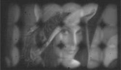
A compound lens of this sort—a so-called “cluster eye”—was created with 21 × 3 elements, each having a thickness of 2 mm, a 4.1°× 4.1° FOV, and an individual image component 192 × 192 µm in size. For reasons relating to the fact that the lens was a first prototype, only the central 8 × 3 channels produced good image components. Seamless stitching of the individual image field was not achieved; however, the individual fields lined up well with each other (see Fig. 2). Resolution was 3.3 LP/°. Introducing ground glass in the intermediate image plane coarsened the image, but increased the FOV and softened the transitions between individual images.Jacques Duparré, one of the Fraunhofer-Institut researchers, notes that making the cluster eye a product will require square microimages for better stitching, a goal that is the subject of intense research. “The existing microimages are round due to not-very-accurately processed field apertures, and due to problems of axial matching of the intermediate image plane with the position of the field-aperture array,” says Duparré. “The first problem will be solved in the next fabrication runs. The second problem is more fundamental, because it is limited by the radius-of-curvature accuracy of the first lens array and, most important, by axial alignment precision. It will be addressed in the next fabrication runs and iteratively solved.”
Other aims are to increase resolution, create absorbing rather than reflecting apertures, and introduce a more-telecentric behavior (less-steep angles in image space), says Duparré.
REFERENCE
1. J. Duparré et al., Optics Exp.13(3) (Feb. 17, 2005).

John Wallace | Senior Technical Editor (1998-2022)
John Wallace was with Laser Focus World for nearly 25 years, retiring in late June 2022. He obtained a bachelor's degree in mechanical engineering and physics at Rutgers University and a master's in optical engineering at the University of Rochester. Before becoming an editor, John worked as an engineer at RCA, Exxon, Eastman Kodak, and GCA Corporation.
