Fluidic zoom lens is fabricated lithographically
Researchers at the University of California at San Diego (UCSD; La Jolla, CA) have been developing fluidic adaptive lenses that focus when fluid is forced between a membrane and a rigid substrate (see Laser Focus World, August 2003, p.11). Now, they have created a zoom version of the lens, as well as a batch-fabrication process similar to that for integrated circuits.1 The lens is aimed at applications that are cost-, size-, and weight-sensitive, such as cameras in personal data assistants, cell phones, notebook computers, and miniature surveillance systems.
Unlike standard bulk-optic zoom lenses that operate by varying the distance between lenses of fixed focal length, the fluidic lens zooms by varying the focal distances of the fluidic front and rear lenses in the system. Biological vision systems (animal eyes) are also tunable through a change in the lens shape, but their lens type is not convertible between convex (positive) and concave (negative); such convertibility is an advantage for zoom-lens designs in which lens spacing is not varied.
The researchers at UCSD have used a UV-lithographic process similar to LIGA (a German acronym for a technique involving lithography, electroforming, and molding). The UCSD approach combines soft lithography and wafer-bonding techniques to fabricate fluidic zoom lenses, reducing manufacturing costs and making zoom-lens arrays feasible.
The fabrication process consists of mold-master fabrication (the mold master can be used repeatedly to fabricate many lens wafers) and lens-device fabrication. The first step in fabrication of the mold master is to lithographically define the positions of the lens chambers and the channels for fluidic inlet and outlet in SU-8 photoresist on a 10.16-cm silicon wafer. These patterns are then transferred to a 4-mm-thick polydimethylsiloxane (PDMS) material using soft lithography, with the thickness of the lens chamber defined by through-hole punching at the lens-chamber positions. The patterned PDMS is then oxygen-plasma bonded to a 10.16 cm silicon wafer. For the design of a 20‑mm lens aperture, the height of the chamber was 4 mm and the PDMS membrane thickness was 60 µm.
Next, two of these PDMS wafers are bonded to a 150-µm-thick glass substrate to form a PDMS-glass-PDMS sandwich structure. Each lens chamber is then filled with 63% sodium chromate solution with a refractive index of 1.5. The integrated zoom lens (upon dicing) or zoom-lens-array element has a total thickness of 8 mm and a lens aperture of 20 mm. The fluidic pressures in the lens chambers are controlled by a battery-powered system consisting of a miniature pump, liquid valves, an electronic control circuit, and a pressure sensor. By dynamically controlling the focal distance of each lens through a change in the fluidic pressure in each lens chamber, the lens is zoomed.
Performance
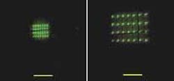
Performance of the fluidic lens was observed by imaging an array of light-emitting diodes (LEDs) fixed at 250 or 1000 mm from the object side of the lens (see figure). For a 30-mm distance to the resulting image, the total physical length (including the image distance) of the optical system was less than 43 mm. Negative pressure creates a plano-concave lens and positive pressure creates a plano-convex lens. The integrated zoom lens was able to form a clear image during zooming for objects at distances greater than or equal to 250 mm. The zoom ratio, defined as the ratio of the maximum and minimum effective focal lengths of the optical system, was found to be two for a fluidic zoom lens with 20-mm aperture. By reducing the lens aperture (easily accomplished by a lithography pattern change), a zoom ratio greater than four could be achieved.
The research team has filed two patents through UCSD, one on the design and realization of the fluidic lenses and the other on the integration of lenses with microfluidic circuits. “Two such tunable lenses can achieve a field-of-view tuning range from 7° to greater than 70°, essentially combining a telephoto system and a wide-angle system in one,” says researcher De-Ying Zhang.

