Spectral imaging evolves to meet biomedical needs
Light-based imaging has extensive applications in medical and biological research with recent advances in spectral imaging opening new avenues for visualizing and recording live specimens. Spectral imaging combines conventional imaging with spectroscopy to accomplish tasks that each cannot perform alone. Data is acquired in a “true color” stack of images, each recording a single spectral channel or “color.”
Researchers have traditionally acquired spectral images using a CCD detector through a series of dielectric filters. Each frame is stored and the composite image is analyzed off-line. To increase the number of spectral data points, expensive automated filters are sometimes used. Each of these filter methods acquires the same image at the first wavelength, and then the next wavelength, the next wavelength, and so on. Depending on the signal strength and the number of acquisitions needed to secure the optimum wavelength coverage, this method can be time-consuming and can use anywhere from 10 to 100 Mbytes of file space before the initial computation is made.
The major drawback to this technique is the inability to take a spectral “photograph.” The very last scan must be completed before a good first impression of the image quality can be obtained. Because each part of the spectrum must be acquired sequentially, deterioration of the image caused by photobleaching often occurs.
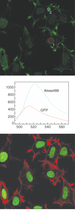
The optical-design and signal-processing capabilities of the emerging generation of spectral- imaging microscopy systems effectively address these types of issues (see Fig. 1). Simultaneous 32-channel spectral-image acquisition over a range of 320 nm at 10-nm spectral resolution is possible using either single or multiple laser excitations. Simultaneous 32-channel acquisition at 5-nm or 2.5-nm resolution is possible at the same speed at a correspondingly reduced spectral range. Diffraction-efficiency-enhancement systems and high-efficiency fluorescence-transmission technology optimize the signal reaching the multi-anode photomultiplier detector, while newly developed dual-integration signal-processing technology speeds up the digitization time. High sensitivity and excellent signal-to-noise characteristics make the high data-acquisition rates necessary for live-cell imaging possible.
Fluorescent labeling in vivo
The use of multiple fluorescent labels has long been commonplace in the study of fixed specimens, and is now becoming established for in vivo studies. Fluorescent proteins are widely used as reporters of transcription in live cells. The goal of spectral imaging in such applications is to collect the optimum signal despite detection noise, system noise, photobleaching, and fluorescent background.
Background fluorescence from any number of causes, including specimen preparation and autofluorescence of the specimen, severely reduces detection of the appropriate signal. With multiple labeled samples, the signal from one fluorophore is often stronger than another and easily spills over to an adjacent channel.
Spectral confocal imaging allows the emission spectra of closely overlapping probes to be unmixed into separate data channels. Most commercial confocal microscopes today have the ability to collect two or three prespecified colors simultaneously. However, there is often a need for more-complete spectral information to allow the detection of more fluorophores or to detect a specific fluorophore.
Background fluorescence from endogenous fluorophores, or from interfering exogenous fluorophores can severely reduce detection or interpretation of the image signal. It can be difficult to separate the signal from multiple fluorescent probes with conventional confocal microscopes because of the overlap of their fluorescence emission spectra. Artifacts due to spillover can be especially troublesome in fluorescence-resonance energy-transfer (FRET) microscopy in which precise localization of the source of the signal is required.
However, it is possible to solve these problems by acquiring the fluorescence spectrum at a high resolution, mathematically separating the signals from each probe, and assigning it to a discrete data channel free from confounding spillover. The result is a “true-color stack” of specimen images, in discrete, continuous, narrow spectral bands.
Not so long ago only three fluorophores were in widespread use, fluorescein, rhodamine, and DAPI, but now there is a plethora of fluorophores available, each with its own unique spectral characteristics. This has caused problems for fluorescence microscopists because the many filter sets required for double- or triple-labeled samples use expensive interference filters and dichroic mirrors that are often difficult to interchange. Collecting the entire spectrum in a “one shot” single pass using a diffraction grating allows the fluorophores to be identified and cleanly separated for analysis by linear unmixing algorithms, and is an essential tool for demanding cellular-biology imaging requirements.
Newer systems like Nikon’s C1si cleanly separate the signals of fluorescent proteins including CFP, GFP, YFP, DsRed, even in combination with closely overlapping antibody conjugates such as Alexa488, Cy3, and others using spectra derived from the image itself or saved to memory as reference spectra (see Fig. 2). Clean separation of the signals of probes from autofluorescence is also possible.
From spinning disk to swept field
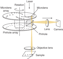
Designed in 1884 by German inventor Paul Nipkow as a way to transmit images electrically, the Nipkow spinning disk uses a pair of spinning metal disks with holes punched in a spiral pattern. In the mid-1990s the Yokogawa Electric Corporation adapted the Nipkow disk for confocal scanning in microscopy. Yokogawa improved excitation efficiency in the system by placing a second disk containing microlenses over the pinhole disk. While this improved illumination efficiency, it did nothing to improve detection efficiency or confocality (see Fig. 3).
The disadvantage of the Nipkow system is that only a single pinhole size is available and it is not well matched to the objective lenses most scientists use for live-cell confocal imaging. In today’s spinning-disk microscopes, an input laser illuminates approximately 1000 of these microlenses, focusing the light through the same number of pinholes, and the multiple “minibeams” are focused by the objective onto the focal plane. As the disk rotates, each beam scans a portion of the focal plane, resulting in every point of the field of view being scanned in a very short time. Emitted fluorescence from each scanned point is collected by the same objective and focused through a tandem pinhole onto a dichroic mirror, and onto the CCD to construct the image.
Performance of spinning-disk microscopes, however, is limited by a lack of synchronization between the spinning disk and the CCD camera. This causes banding patterns to be superimposed onto the image. Banding patterns are prominent when short CCD exposure times are used, because the partially scanned Nipkow image represents a greater proportion of the total CCD exposure. Because many processes require rapid frame rates, this is a common problem. Swept-field confocal (SFC) microscopy, was developed to address many of the drawbacks inherent in scanning-disk technology.
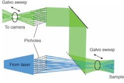
As with a Nipkow disk microscope, the SFC sweeps an image of an array of pinholes over the field, and the pinholes remain stationary (see “How swept-field confocal microscopy works,” p. 89). A galvo mirror and piezo mirror sweep the pinhole images across the specimen. These points are then “reswept” into a CCD device capturing the image (see Fig. 4). Four pinhole aperture sizes can be selected from 30 to 90 µm. Also 35- and 70-µm slit apertures can be chosen. The user selects the most appropriate pinhole or slit for the experiment. This laser confocal-microscope technique enables dynamic live-cell confocal imaging in point-scan mode for high-resolution data acquisition at frame rates of up to 260 frames/s, and in slit-scan mode at acquisition frequencies exceeding 1500 frames/s, while minimizing specimen bleaching.
Swept-field confocal microscopy monitors and records rapidly occurring events in millisecond time in living cells without compromising spatial resolution. It simultaneously controls high-frequency low-intensity illumination to reduce photobleaching and phototoxicity.❑
How swept-field confocal microscopy works
Swept-field confocal microscopy combines tandem-scanning technology with galvanometer- and piezo-controlled scanning mirrors. The illuminating photons are focused through a row of 32 stationary pinholes over the specimen so each point in the specimen is illuminated 300 times/s. The emission photons are descanned and focused through a complementary row of pinholes on the image side, and from there onto the face of a high sensitivity CCD camera. Because the pinholes are stationary, the plate containing them can contain four rows of pinholes, with the pinhole size for each row selected to maximize both axial and lateral resolution for the most commonly used confocal objective lenses.
The plate also contains two slits of different size allowing data acquisition at fast frame rates. Users can trade between scanning apertures to obtain the most advantageous balance between speed, resolution, and sensitivity. Swept-field confocal microscopes take advantage of up to six acousto-optical, tunable-filter-modulated laser lines for single- or multichannel sequential data acquisition. Advantages of SFC systems also include reduced back reflections from incoming light, a stationary pinhole pattern resulting in easily selected pinhole sizes and a slit mode for ultrafast confocal imaging modes.


