Free-space laser communications, in which a laser beam is sent directly through the air instead of through a fiber, is already being used successfully over short distances when fiber links are either physically or economically impractical. Recently, the idea of extending the range to tens of kilometers has been explored. However, as the path length that a laser beam must propagate increases, performance becomes increasingly susceptible to several deleterious effects caused by atmospheric turbulence. These effects decrease the receiver signal-to-noise ratio, ultimately resulting in a large bit-error rate (BER).
A possible solution to this problem involves adaptive optics (AO)-manipulating the laser-beam phase with flexible mirrors in real time to correct for the atmospheric effects. The modeling of the laser-beam propagation through the atmosphere, and including AO components in the system, allows performance to be estimated before a single component of the physical system is purchased and provides important physical insight.
Component modeling
Simulations of AO systems for free-space communications require that several distinct components be accurately modeled (see Fig. 1).1 The starting point is to model the propagation of the communications laser beam through the atmosphere. First, the laser beam is represented as a single-frequency electromagnetic wave with amplitude E0 and phase L. The atmosphere is modeled as a set of phase sheets, each sheet representing the sum of all the distorting phases in a slab of atmosphere of thickness L (see Fig. 2). The light propagates between each sheet as if in a vacuum using a simple Fresnel propagation kernel, but when it encounters a new sheet, the phase of that sheet is added to the phase front of the laser light before propagation to the next sheet. This approximation is valid as long as the light rays do not cross in the distance L. For a horizontal path, this usually means creating an atmospheric screen for every 100 to 200 m of path length, depending on the strength of turbulence. For slant paths and vertical paths, as in astronomy, for example, fewer screens are required, as the turbulence falls off rapidly with height above the ground. The spectral distribution of the turbulence is taken to be Kolmogorov, or algorithmic randomness. The laser is apertured at the last screen by the receiving telescope of diameter D. Wind can be simulated by moving the phase sheets perpendicular to the laser direction.
The second component to be modeled is the wavefront sensor. Several techniques can be used to measure the phase of a laser beam (see Laser Focus World, April 2004, p. 77) and we begin with a Shack-Hartmann wavefront sensor (SHWFS). At the receiver, the light is broken up into several small elements by a lenslet array. If a charge-coupled device (CCD) is inserted at the focus, the place where the focused spots hit determine the laser phase in the small area the size of an individual lenslet at one point across the beam. For a relatively small number of actuators on the AO of interest, it is quite straightforward to associate each subaperture of the SHWFS with the corresponding actuator on the adaptive optic, which is the third main component to model in the system. As a side note, a common measure of the turbulence, known as the Fried parameter, r0, can be obtained directly from the statistics of the motion of the individual spots that dance about a point where they rest when a perfect plane wave is sent through the system.2 A small r0 (approximately 1 mm) is associated with severe turbulence, whereas r0 on the order of several centimeters is considered mild turbulence.
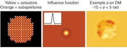
Several methods can be used to correct the phase of the laser light; we will concentrate on deformable mirrors (DM). A particularly interesting device is the microelectromechanical systems (MEMS) DM. A relatively recent invention, MEMS mirrors consist of several tiny mirrors, each a few hundred microns square, to be tied together on a millimeter-sized grid that can be moved independently on a 10-millisecond time scale. If a thin membrane is placed over each actuator, pushing on one mirror results in a slight influence on neighboring pixels, which is modeled by assuming an influence function for the reflecting surface (see Fig. 3). By sensing the phase quickly, and applying the opposite of this phase on the received beam, a nearly flat wave front results, allowing improved focusing of the received light.
FIGURE 3. In modeling a MEMS mirror, the effect of each pixel or deformable-mirror actuator upon its neighbors within the Shack Hartman wavefront sensor (left) can be modeled by assuming an influence function (middle) based on the laser-propagation-induced phase of each DM (right).
Modeling atmospheric performance The performance of an AO system is usually determined by how close the corrected-beam Strehl ratio is to 1. For our purposes, Strehl is taken to be the ratio of the peak laser intensity compared to the theoretical diffraction-limited peak. By accurately modeling the atmosphere, the wavefront sensor, and the deformable mirror, an estimate of the received laser power available for coupling into a detector or fiber can be found. Because the effects of wind are incorporated into the computational model (simply by moving the phase sheets as shown in Fig. 2) various time-dependent phenomena associated with the AO loop can also be investigated with these simulations. Intuitively, one expects that the faster the wind, the quicker the AO system must respond to correct the wave fronts. In fact, Fried and Greenwood derived that for a fixed time delay between corrections, the Strehl ratio decreased exponentially by the 5/3 power of the wind velocity times the delay, divided by the Fried parameter.3, 4 This relationship has been verified for a wide range of simulation parameters.
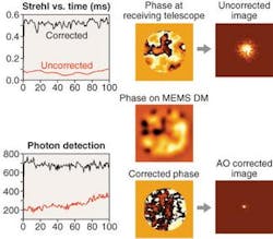
Atmospheric modeling can also be useful in designing an experimental test bed for laser communications. By etching glass plates with the same computer-generated Kolmogorov phase patterns used in the simulations, one can simulate kilometers of atmosphere on an optical table of approximately two meters in length. If the plates are separated by a few feet, and are set spinning, they can also simulate the effect of wind. Systems can now be designed under realistic, controlled conditions, and the outcome is known a priori by simulation. Repeatable atmospheric experiments can now be done. Recently, Kevin Baker at LLNL successfully developed a 1024 MEMS-based AO system on just such a test bed using an interferometeric �phase conjugate engine� (as opposed to the SHWFS) in compensated receiver configuration running at 580 Hz.5 By propagating a laser through the spinning phase plates, he obtained increases of factors of 50 in Strehl (see Fig. 4). In addition, by debugging the system in the laboratory, actual field-deployment time was minimized.
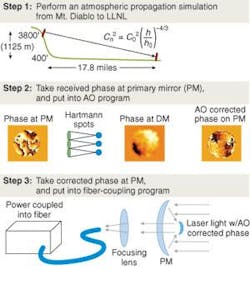
With longer-range laser propagation¿for example, the 28-km slant path that the Secure Air-Optic Transport and Routing Network (SATRN) used from LLNL to the top of Mount Diablo¿alternate methods must be used because the size of the beam (many meters wide at the end of its path) makes the size of the phase sheets prohibitive (see Fig. 5). Here, Talanov transformations are used, in which the number of grids on the screens are held fixed, but the distance between nodes increases as the beam propagates farther from the transmitter. Strong turbulence and severe scintillation dominate this regime, but Johnson and Ruggerio have demonstrated 2.5 Gbit/s over this link.6
ACKNOWLEDGMENT
This work was performed under the auspices of the U.S. Department of Energy by the University of California, Lawrence Livermore National Laboratory under contract W-7405-Eng-48.
REFERENCES
1.S. C. Wilks et al., Proc. SPIE 4821, 121, (2002).
2.D. L. Fried, J. OSA 55, 1427 (1965).
3.D. L. Fried, J. OSA A 7, 1224 (1990).
4.D. P. Greenwood, J. OSA 67, 390 (1977).
5.K. L. Baker, E. A. Stappaerts, D. Gavel, S. C. Wilks et al., Appl. Optics 43, 5585 (2004).
6.G. W. Johnson et al., Proc. SPIE 4821, 283 (July 2002).


