GRENOUILLE measures spatio-temporaldistortions
Ultrashort laser pulses lead difficult lives. They are routinely stretched, amplified, and then compressed by several orders of magnitude-a stressful experience, to say the least. And in all of these stages of optical torture, pulses endure traumas from which they often never completely recover.
What are these ultrafast-optical “personality disorders”? They are spatio-temporal distortions: idiosyncrasies in a pulse’s spatio-temporal behavior that significantly complicate its interactions. While we generally desire that the electric field of a mature pulse has achieved independence of its temporal and spatial factors-that is, pulses with spatio-temporal distortions are those that have not. This complication is a big one, although many prefer to remain in denial on the subject. Fortunately, a simple diagnosis and remedy for these disorders has recently become available.
Causes of spatio-temporal distortions
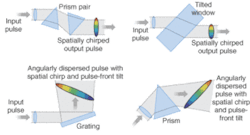
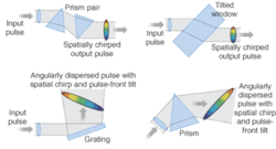
The two most common such afflictions are spatial chirp and pulse-front tilt (see Fig. 1). A pulse is said to have spatial chirp when its average wavelength varies transversely across the beam, in analogy with temporal chirp, in which the pulse frequency varies with time.1 The main source of spatial chirp in an ultrafast system is the pulse compressor-a sequence of four prisms (or gratings) that is a standard component in essentially all ultrafast lasers and apparatuses. After the first two prisms, there is considerable spatial chirp. While two additional prisms in principle later remove this effect, in practice they typically don’t completely do so unless aligned perfectly. Spatial chirp also results from many other common components, such as a window with a wedge.
A pulse is said to have pulse-front tilt when its contours of constant intensity tilt at an angle to the propagation direction.2 Pulse-front tilt also usually results from angular dispersion and so occurs in pulse stretchers and compressors. But it can also result from the combination of spatial and temporal chirp, in the absence of angular dispersion.2 Also, pulse shapers incorporate dispersive components and therefore also cause these distortions.
The consequences of spatial chirp and pulse-front tilt can be severe. Both distortions lengthen the pulse and hence also reduce its intensity. And because a beam’s spatial profile reverses on reflection, any experiment using such a pulse will have very different temporal and frequency characteristics depending on the relative number of reflections that the excitation and probe beams make on their way to the sample medium.
The need for a convenient diagnostic
A few techniques for measuring these distortions have been proposed. Unfortunately, these devices are either nonquantitative or very complex. Indeed, some complex methods are as likely to introduce these distortions as to measure them. A spatially resolved spectral measurement would, in principle, measure spatial chirp, but aberrations in spectrometers mimic spatial chirp, so such measurements are not always trustworthy. Most pulse-measurement devices do not see pulse-front tilt and actually report a shorter pulse length than would be experienced by an experiment using such pulses. Other techniques for measuring pulse-front tilt actually measure angular dispersion instead, in the mistaken belief that the two effects are equivalent.
If a disorder can’t be diagnosed, it can’t be cured. As a result, ultrashort laser pulses are generally badly afflicted with spatio-temporal distortions. Unfortunately, ultrashort-pulse diagnosticians (including the authors of this article) have been a bit obsessed with the dependence of ultrashort pulses on time alone.3
The only ultrashort-pulse diagnostic available for many years was the now-obsolete autocorrelator, an inadequate attempt to measure the pulse intensity versus time. It yielded only a blurry picture of the pulse intensity (hiding the pulse’s intensity structure), and it gave no information at all about the pulse phase versus time-never mind spatio-temporal distortions.
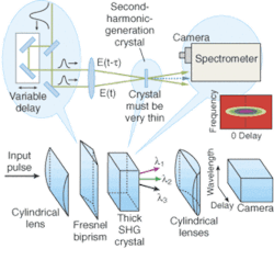
Fortunately, we can now fully measure the time-dependent intensity and phase of even the shortest pulses. The most popular such diagnostic is frequency-resolved optical gating (FROG).3 The FROG technique involves splitting a pulse into two, variably delaying one pulse with respect to the other, crossing them in a nonlinear optical medium, and measuring the nonlinear optical-signal pulse spectrum versus delay (see Fig. 2). The result is a spectrogram of the pulse. User-friendly, reliable, and fast (commercially available) phase-retrieval algorithms yield the pulse intensity and phase versus time and frequency. With reliable checks that confirm its results, FROG is a versatile technique that can even measure noisy trains of extremely complex pulses.
Simplifying FROG
Recently, we introduced a simple version of FROG.4 Called GRating-Eliminated No-nonsense Observation of Ultrafast Incident Laser Light E-fields (GRENOUILLE), it avoids essentially all the complex components of traditional ultrashort-pulse diagnostics, replacing the beamsplitter, delay line, and beam-combining optics with a single element, a Fresnel biprism, which splits the input pulse in two and then automatically recombines the two pulses at the crystal (see Fig. 2).4, 5 It also replaces the usually extremely thin second-harmonic-generation (SHG) crystal and the spectrometer with a thick crystal, which gates one pulse with the other and then spectrally resolves the gated pulse.
In the GRENOUILLE device, a cylindrical lens produces a line focus at the SHG crystal; the two pulses produced by the Fresnel biprism cross in the crystal at an angle (see Fig. 3). As a result, delay is mapped onto horizontal position at the crystal. The wavelength that achieves phase-matching in the crystal varies with (vertical) crystal incidence angle. Because the beam is focused into the crystal, the beam divergence is large in the vertical direction, so that all wavelengths of interest phase-match for some angle. A cylindrical lens with horizontal power images the crystal onto the camera, mapping delay onto horizontal position at the camera. Meanwhile, a cylindrical lens with vertical power maps the crystal vertical output angle (and hence wavelength) onto vertical position at the camera to achieve a full FROG trace of SHG signal pulse energy versus delay and wavelength.
Handling spatio-temporal distortions
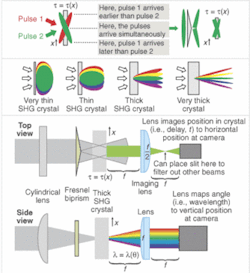
Surprisingly, GRENOUILLE also measures the pulse spatial chirp and the pulse-front tilt. In the absence of spatio-temporal distortions, the GRENOUILLE trace is always symmetrical with respect to delay. But spatial chirp causes a shear in the GRENOUILLE trace directly proportional to the spatial chirp (see Fig. 4).6 And pulse-front tilt displaces the trace in delay by an amount directly proportional to the pulse-front tilt.7 Both of these distortions in the trace are easily identified either by eye or by a modified pulse-retrieval algorithm. Even better, GRENOUILLE is the most sensitive measure of pulse-front tilt ever devised. With a few minor additions, a typical GRENOUILLE device can measure essentially every characteristic ever desired about an ultrashort pulse: the intensity and phase versus time, the spectrum and spectral phase, the spatial chirp, the pulse-front tilt, and the beam spatial profile.
With this new measurement power, we have discovered that nearly all ultrashort pulses, whether from laboratory or commercial lasers, contain at least some spatio-temporal distortions, and occasionally these effects are quite severe.
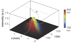
- The crystal yields the sum frequency of the two pulses, so spatial chirp causes a variation of this signal wavelength versus transverse position (that is, versus delay). This yields a tilt or shear in the otherwise symmetrical GRENOUILLE trace proportional to the spatial chirp. Pulse-front tilt causes the zero-delay point to shift laterally (top right; a pulse with no pulse-front tilt is green, while a pulse with tilt is red). A dysfunctional pulse with temporal chirp, spatial chirp (dë0/dx =0.92 nm/mm), and pulse-front tilt (ø = c dt0/dx = 12 mrad) was measured using GRENOUILLE (bottom). The color indicates the pulse instantaneous frequency, scaled to comprise the visible range. This pulse may be pretty to look at, but it could be deadly to an experiment that uses it.
REFERENCES
1. X. Gu et al., Opt. Comm. 242, 599 (2004).
2. S. Akturk et al., Opt. Express 12, 4399 (2004).
3. R. Trebino, Frequency-Resolved Optical Gating: The Measurement of Ultrashort Laser Pulses (Kluwer Academic Publishers, Boston, 2002).
4. P. O’Shea et al., Opt. Lett. 26, 932 (2001).
5. www.swampoptics.com
6. S. Akturk et al., Opt. Express 11, 68 (2003).
7. S. Akturk et al., Opt. Express 11, 491 (2003).
RICK TREBINO is a professor of physics, XUN GU is a post-doctoral SCHOLAR, and SELCUK AKTURK, , PABLO GABOLDE, AND ZIYANG WANG, are graduate students at the Georgia Institute of Technology, School of Physics, 837 State St., Atlanta, GA 30332; e-mail: [email protected].
