Beam-shaping optics deliver high-power beams
Peter Y. Wang
Recent commercial availability of high-power laser-diode arrays has brought about the need for novel beam-shaping methods using lenses, fiberoptics, mirrors, and other optics.The development of laser diodes that deliver more than 10 W of output has changed the picture of the laser market. High-power devices now offer many advantages over conventional lasers of similar power levels, such as carbon dioxide or lamp-pumped Nd:YAG lasers. Their high efficiency (>30% wall-plug efficiency) promotes compact size as well as simplicity in power supply and cooling, which make the laser diode an attractive alternative for many applications.
Beam delivery is a crucial step in the successful and efficient use of high-power laser diodes. The issue of high brightness in high-power laser-diode beam delivery has been particularly challenging for OEM and equipment manufacturing applications. Improving beam delivery to achieve output with high brightness, high power, and high optical quality will certainly benefit the extensive use of these energy-efficient laser devices.
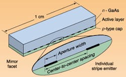
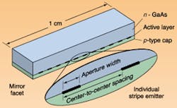
The difficulty with high-brightness delivery of high-power laser-diode beams stems from the geometry and structure of these devices. A high-power laser diode is normally found in the form of a laser-diode array (LDA), comprised of a number of emitting elements, with each element being very thin and narrow (about 1 x 3.5 µm), emitting less than 300 mW (see Fig. 1). In a typical array, the emitting surface is a narrow line of about 20 segments with multiple emitting elements. Thus, a high-power LDA has a broad-area light-emitting aperture of about 1 cm x 1 µm. With such a configuration, some commercially available high-power LDAs can provide 40 to 50 W of power. With good cooling structure, power as high as 270 W has been achieved in the laboratory.1 Much higher power can be achieved by layering high-power LDA bars in stacks (see "Practical 100-kW-class diode arrays emerge," p. 103).
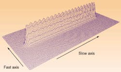
The raw output beam from an LDA is highly divergent and suffers from two asymmetriesastigmatism and an elliptical beam profile. The divergence angles are different in two axes, the so-called "fast axis" and "slow axis." Typical fast-axis divergence is about 40° full-width half-maximum (FWHM) and slow-axis divergence is about 10° FWHM. Sometimes the divergence can be as high as 50° x 15°. When the noncircular, astigmatic, incoherent beam from the LDA is focused, the beam spot is greatly elongated, which is undesirable for most applications (see Fig. 2). Also, low brightness of the beam spot results from the "dead" spacing in the emitter configuration. As a consequence of poor beam quality and low brightness, high-power laser diodes have not been used in traditional applications such as cutting and high-speed, deep-penetration welding.
Beam shaping and high brightness
The most convenient way to measure the beam quality of an LDA is to characterize the beam parameter product (BPP) or Lagrange invariant, defined as q0 x W0, where q0 is the divergence angle and W0 is the beam dimension. Thus, for an LDA with a divergence of 40° x 10° (where 1° = 0.017 rad), the BPP in the fast axis is 1-mm mrad, while that in the slow axis is 1700-mm mrad. The divergence in the fast axis can be collimated to a large extent by using cylindrical lenses. To improve the beam quality in the slow axis, microlens arrays can be used. In general, slow-axis correction is less successfulonly about 50% of the initial divergence can be collimated. To avoid the overlap in the emission plane, other more complex methods of slow-axis collimation exist for LDAs with smaller pitch (the distance between the center of two adjacent emitters).
Currently, the most efficient way to significantly improve beam quality is to combine reshaping and collimation. Using special optical elements, the elongated beam from an LDA is divided into n pieces and rearranged into a more easily focused circular beam. Such beam shaping decreases the BPP by n-fold in the slow axis and increases it by the same ratio in the fast axis.
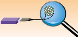
The most classical and straightforward method for LDA beam shaping uses a cylindrical lens to focus the laser beam into a fiber bundle array (see Fig. 3). The light from each discrete emitter of the LDA is converged into a circular beam. Such devices have been on the market for several years. High brightness cannot be achieved with this method, however, because the laser mode of the LDA emitter does not match the mode of optical fiber. Moreover, the brightness of the LDA is further decreased after the fiber bundle. For example, a typical 20-W array with an emitter area of 1 cm x 1 µm and divergence angle of 10° x 40° has a brightness of 1.6 x 10⁶ W/cm2 str. When coupled with a 0.6-mm fiber bundle with a numerical aperture of 0.18 to give a fiber output of 16 W, the brightness drops to only 5 x 10⁴ W/cm2 str.
Another straightforward way to improve the beam shape of a high-power LDA is to use stacks. A stack consists of several LDA bars mounted on top of each other, separated by heat sinks. Multiple fast-axis collimation enables up to 1 kW of output from a 1.5-mm fiber without polarization or wavelength coupling, assuming a power density of 104 W/cm2 as specified by the high-power laser delivery systems of Rofin Sinar (Hamburg, Germany). By using stacks, the BPP in the fast axis is increased, but it is unchanged in the slow axis. Therefore, the beam shape with this method is still far from circular, and it is more suitable for cases involving more than 1 kW of power. Moreover, "dead" spaces due to the heat sinks between emitters limit brightness.
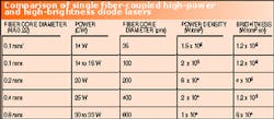
To further improve the beam quality and brightness, rather sophisticated beam-rearrangement mechanisms are normally used. Two typical examples are the step mirror approach used by the Fraunhofer Institute for Laser Technology (Aachen, Germany) and the two-reflector approach from researchers at the University of Southampton (Southampton, England).2, 3 Both methods have been used commercially for making fiber-coupled laser-diode devices. Also, researchers at Apollo Instruments recently developed several new efficient approaches for beam shaping. With the support of the US Air Force Research Laboratory (Kirtland Air Force Base, NM), a series of fiber-coupled laser diodes was commercializedsome with record brightness (see table). Apollo's F14-XXX-1 has a BPP of 11-mm mrad at 16 W with a brightness greater than 1 MW/cm2 str, which was previously thought difficult to achieve. The brightness and power density shown in the table are derived from products using a single high-power laser-diode bar. As is commonly done, it is possible to further increase the overall power by a factor of two or more for the same beam quality by polarization and/or wavelength coupling of two or more high-power laser bars. The beam is delivered through a single optical fiber, creating a perfectly circular Gaussian spot. The beam quality is therefore much better than that obtained simply by beam shaping and focusing. With an appropriate focusing optical head, the beam from the fiber can be focused on the work piece or, if necessary, shrunk into a smaller beam spot with an enlarged numerical aperture.
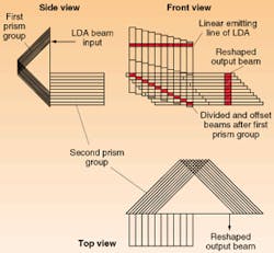
To better understand the beam-shaping process, closer examination of one of Apollo's approaches is helpful (see Fig. 4). In one configuration, two groups of prisms are used to divide and rearrange the beams from the LDA. In both of the prism groups, each prism is offset from the next prism along the hypotenuse by a certain distance. The first prism group divides the linear emission into multiple sections along the slow axis. The beams enter from the hypotenuse surfaces of the prisms, reflect twice in the prisms, and then exit from the hypotenuse surfaces with each beam offset from the other sequentially due to the prism offset. The beams then enter the second prism group, and are rearranged into an output beam by the same principle. As a result, the linear beam of the LDA can be reshaped into a beam spot with a similar BPP in both directions. For n = 10, the BPP of the beam spot can be reduced by 10 times in the slow axis and increased by 10 times in the fast axis.
In the past, the applications of high-power laser diodes have been limited to those that do not require extremely accurate focusing of light at high-power densities, such as in plastics welding. With the availability of high-brightness devices, much wider applications are anticipated. At power densities above 106 W/cm2, metal marking or drilling becomes possible with direct use of high-power laser diodes.
REFERENCES
- Industrial Laser Solutions, January 2000, p. 6.
- J. R. Hobbs, Laser Focus World, May 1994, p. 46.
- B. R. Marx, Laser Focus World, May 1998, p. 32.
PETER Y. WANG is vice president and marketing manager at Apollo Instruments Inc., 18019 Sky Park Circle, Suite F, Irvine, CA 92614; e-mail: [email protected].
