OPTICAL FABRICATIONMagnetorheological finishing produces calcium fluoride lenses for 157-nm lithography, overcoming crystalline anisotropy and producing nanometer-scale surface figure.
Don Golini, Mike DeMarco, William Kordonski, and John Bruning
Semiconductor lithography at 157 nm poses many difficult challenges for the large-scale manufacture of lithographic optics. Overall requirements for precision increase by 20% over 193-nm-based systems and nearly 40% over 248-nm-based systems simply because of the reduction in wavelength. Fused silica, traditionally the primary material used in deep-ultraviolet photolithography at 248 and 193 nm, has undergone decades of optimization for this application and has several established suppliers; however, fused silica is nearly opaque at 157 nm except when doped with fluorine. Transmission of fluorine-doped fused silica is too low for lithographic lens applications (although quite suitable for photomasks; see "Modified silica transmits vacuum UV," p. S15).
The only materials with sufficient transmissivity at 157 nm are single-crystal fluorides such as calcium fluoride, barium fluoride, and lithium fluoride. Calcium fluoride is the most robust and highly developed of the fluorides; barium and lithium fluoride are highly hygroscopic and much more difficult to work. Recent breakthroughs in optical fabrication technology now enable high-volume production of ultrahigh-precision fused silica and calcium fluoride optics.
Why calcium fluoride over fused silica?
Fused silica is the primary optical material used for 248- and 193-nm lithography. Calcium fluoride is used as a companion material to fused silica for color correction at 193 nm and is also used in areas of high flux because of its high laser damage resistance. Fused silica has more than 99%/cm of bulk transmission at 193 nm; at 157 nm, however, its transmission drops to less than 5%/cm. On the other hand, calcium fluoride has a bulk transmission of greater than 98%/cm at 157 nm. Calcium fluoride is clearly better than fused silica at this wavelength, but still represents a significant relative reduction in transmission from materials at 193 nm, considering that a typical lithographic projection lens might have 60 surfaces and nearly a meter of optical path.
FIGURE 1. In a magnetorheological finishing (MRF) system, polishing forces are applied to the workpiece via a magnetorheological fluid whose stiffness can be varied, creating a tailored shear-stress distribution.
The need to maximize throughput and quality is driving even the illumination systems to be made to a quality approaching that of the imaging system (1- to 10-nm root-mean-square [rms] figure accuracy, 0.1- to 1-nm rms microroughness), further increasing demand for high-grade material and deterministic processing and manufacturing techniques. Requirements for extremely low stress birefringence and high homogeneity (on the order of 0.1 to 1.0 parts per million) have placed new levels of difficulty on the industry, while larger optical-element diameters exacerbate the shortage of the high-quality material necessary for stepper and scanner lenses.
Difficulties polishing calcium fluoride
In conventional polishing, material removal is accomplished by applying a normal load to a flat or spherical polishing lap that is positioned on top of a rotating workpiece with a loose abrasive slurry between the two. The primary purpose is to apply constant pressure and velocity at all points of the workpiece surface to remove material uniformly. This technique is quite successful when the workpiece material is homogeneous amorphous glass.
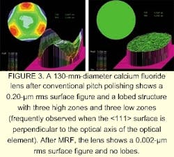
When polishing single-crystal material such as calcium fluoride, however, hardness is dependent on crystal orientation; thus, material removal is anisotropic. When the optician applies techniques to calcium fluoride that have been optimized over many years for optical glass, it becomes difficult to polish spherical surfaces with small figure errors, particularly steeply curved surfaces. The result is often a lobed structure with three high zones and three low zones when the crystal's <111> plane is perpendicular to the optical axis of the element.
Producing ultraprecision optics
The optics industry has seen dramatic advances over the past decade. The use of computer numerically controlled (CNC) equipmentvirtually unheard of prior to 1990is now pervasive in most large and small optics shops worldwide. Such technology has played a significant role in automating the production of optical components, with capabilities to take a raw blank through generating, rough and fine grinding, polishing, and centering in a matter of minutes. This approach satisfies the majority of the manufacturing needs of the commercial optics industry. But its end result is just the starting point for lithographic lenses. Once a lens is at l/10 peak-to-valley surface figure, it typically will be handed off to the "pitch room," where master opticians perform their craft to reach limits of precision that most would consider impossible. The stringent demands on surface figure and finish to a few nanometers are difficult for most to comprehend, but remarkably are achievable by hand-polishing techniques and superb metrology. This polishing process has changed very little from the basic approach set forth by Sir Isaac Newton in the late 1600s.
Pitch polishing takes much longer than with modern CNC methods and requires great operator skill. Many factors determine the total time, but variation characterizes most every aspect of final polishing. Uncontrollable variables include polishing pad material, polishing abrasive, slurry properties, temperature, equipment type and setup, and optician skill level and experience, to name a few. These problems exacerbate the job for cost accountants and production planners, particularly since stepper or scanner lenses costing $0.5 million to $1.5 million are often the critical path items for lithographic systems costing $5 million to $15 million. The semiconductor industry's notoriously cyclic behavior creates a difficult situation for training and retaining a sufficient staff of highly skilled, experienced, and qualified artisans for the periods of highest demand.
Magnetorheological finishing
An alternative precision polishing method called magnetorheological finishing (MRF) has been developed to overcome many of the fundamental limitations of traditional finishing techniques. Magnetorheological finishing is a deterministic subaperture finishing process that has become an enabling technology over the past several years for the production of ultraprecision optics. The technology has a demonstrated ability to produce optical surfaces with an accuracy better than 30-nm peak to valley and surface microroughness less than 1 nm on optical glasses, single crystals (calcium fluoride, silicon), and glass-ceramics.
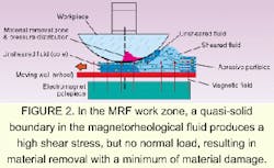
FIGURE 2. In the MRF work zone, a quasi-solid boundary in the magnetorheological fluid produces a high shear stress, but no normal load, resulting in material removal with a minimum of material damage.
At the heart of MRF is a magnetorheological polishing fluid that is used to preferentially polish based on dwell time, with a typical removal function area of 1 cm2. The process methodology characterizes the surface errors in the workpiece and deconvolves the removal function with an empirically determined error function to create dwell time instructions for the process. The removal function is extremely stable because removal rate correlates with fluid viscosity, which is continuously monitored and controlled to ±1%. The MRF fluid forms a polishing tool that is perfectly conformal and capable of polishing high-precision spheres and flats, aspheres, optical surfaces with square or rectangular apertures, prisms, and even cylindrical optics.
Deterministic polishing with MRF
The success of MRF for volume production of ultraprecision optics is a result of its determinism or predictability. This is primarily accomplished through a removal mechanism that is significantly different from that of conventional polishing. The mechanism of material removal in conventional pitch polishing is achieved through the application of normal forces transferred through a soft lap/abrasive system. The relative motion of the workpiece and the lap, combined with an applied pressure and the chemical activity of the slurry, create the conditions for polishing.
FIGURE 3. A 130-mm-diameter calcium fluoride lens after conventional pitch polishing shows a 0.20-µm rms surface figure and a lobed structure with three high zones and three low zones (frequently observed when the <111> surface is perpendicular to the optical axis of the optical element). After MRF, the lens shows a 0.002-µm rms surface figure and no lobes.
In MRF, material removal is accomplished through hydrodynamic forces resulting from the flow of magnetorheological fluid. In contrast to conventional polishing, normal surface stress is not dominant in MRF; rather, energy is supplied via surface shear stress. Shear stress is generated using the properties of a magnetorheological polishing fluid that is deposited by a nozzle on the rim of a rotating wheel, which transports the fluid to the workpiece surface (see Fig. 1). The wheel rim and the surface to be polished form a converging gap exposed to a magnetic field. The moving wall, which is the rim surface, creates a flow of magnetically stiffened polishing fluid through the converging gap, generating a unique pressure distribution that is associated with an unsheared fluid core, which is attached to the moving wall (see Fig. 2). A quasi-solid moving boundary is effectively formed very close to the surface of the workpiece resulting in high shear stress in the contact zone and material removal over a portion of the workpiece surface. Material removal is enhanced by nonmagnetic abrasive particlesconstituents of the slurry that are forced out to the polishing interface by a magnetic field gradient.
The fluid viscosity, velocity, magnetic field, and workpiece positioning accuracyall of which can be controlled to high precisiondetermine the shear stress distribution and magnitude. Since removal rate is proportional to shear stress, a stable removal function is achieved. The removal function (size and removal rate) can be adjusted by changing simple controllable parameters such as wheel speed, lens positioning in the fluid, or magnetic-field intensity. Relatively high, stable removal rates (nominally 5-µm/min peak removal rate within the removal function) are achieved on calcium fluoride while creating a smooth, damage-free surface finish. Unlike conventional polishing in which normal loads can result in scratching, there is no normal load created with MRF.
Advantages of using MRF
Because a deterministic computer-controlled subaperture lap is used, MRF has some unique benefits for polishing calcium fluoride optics. As a result of crystal anisotropy, a small-tool deterministic polishing process is required to compensate for the hardness or removal rate variation. For example, if a crystal were polished with MRF assuming a uniform removal rate, the resulting surface would have three low spots and three high spots equally distributed about the axis. To compensate, these lobing errors on the element surface are interferometrically mapped; software then deconvolves the lobing errors into a unique removal rate map over the element surface, "teaching" the MRF-based polisher how to modify the dwell time or removal at each point on the surface. In a second iteration, the software adjusts the dwell times appropriately to compensate for the material property variations. This requires significant variations in velocity (or dwell) during every revolution of the workpiece. The spindle rotation rate actually modulates to dwell longer at the harder crystal orientations and less at the softer orientations. This approach is extremely powerful. In the future, if the crystal structure and anisotropy could be precisely characterized before polishing, the two-iteration feedback approach could be reduced to a one-iteration compensation technique.
Nearly all modern lithographic lens designs incorporate aspheric surfaces. With higher absorption at 157 nm, aspheres offer a significant advantage because they help designers reduce the number of required optical elements. Fewer elements improve system transmission and reduce material needs. Magnetorheological finishing is one of the few deterministic processes capable of reaching high figure accuracy on aspheric surfaces, particularly on calcium fluoride. Used in production environments since 1998, MRF equipment is being used to achieve nanometer-scale surface figure on both fused silica and calcium fluoride (see Fig. 3). The technology solves many large-volume production challenges for the lithography industry, and can meet the stringent demands that 157-nm lithography requires of optical material, surface figure and finish, and optical manufacturing throughput.
DON GOLINI is president and CEO, MIKE DEMARCO is marketing manager, and WILLIAM KORDONOWSKI is R&D manager of QED Technologies, 1040 University Ave., Rochester, NY 14607; e-mail: [email protected]. JOHN BRUNING is president of Corning Tropel, 60 O'Connor Rd., Fairport, NY 14450; e-mail: [email protected].


