Pulse spreading caused by dispersion is the prime limit on fiber bandwidth, so dispersion compensation offers an obvious way to increase transmission capacity. Conversely, the need for dispersion management increases with data rate and transmission distance. The impact of dispersion increases with the square of the data rate. For 2.5-Gbit/s systems, external modulation at the laser transmitter generally limits spectral width enough to control dispersion. However, 10-Gbit/s systems typically need dispersion compensation beyond several hundred kilometers, and 40-Gbit/s systems will require compensation over much shorter distances. A fiber that could carry 2.5-Gbit/s signals as far as 1000 km without compensation would require compensation after 4 km at 40 Gbit/s.
Two separate effects contribute to pulse spreading in single-mode fiberchromatic dispersion and polarization-mode dispersion (PMD). Chromatic dispersion is larger in magnitude but easier to compensate for in transmission systems. Polarization-mode dispersion is smaller but compensation is much harder, and system performance can suffer if PMD accumulates to 10% to 20% of the bit interval, a level at which chromatic dispersion has little impact. Future 40-Gbit/s systems will require management of both types of dispersion.
Types of dispersion
Both chromatic dispersion and PMD cause pulse spreading in single-mode fibers, but the underlying mechanisms, dependence on distance, and techniques for compensation are different.
Chromatic dispersion arises from the wavelength dependence of the speed at which light signals travel through an optical fiber. Every pulse contains a small but finite range of wavelengths. Their propagation speeds differ only slightly, but fiber systems can be very long. Pulse spreading becomes a problem when it reaches a significant fraction of the bit interval, which is only 100 ps at 10 Gbit/s—or a distance of roughly 2 cm in a glass fiber. A speed difference of only 10-8 can produce that much dispersion over a distance of 2000 km. Chromatic dispersion increases with the range of wavelengths in the signal and the distance, so it is measured in picoseconds per kilometer of fiber length per nanometer of source bandwidth.
Chromatic dispersion is the sum of two components: material and waveguide dispersion. Material dispersion arises from the change in refractive index with wavelength in silica, and is little affected by fiber doping. Waveguide dispersion arises from the distribution of light within the core and cladding of the fiber, and is easily changed by altering the refractive-index profile. Chromatic, material, and waveguide dispersion can have positive or negative signs, so the two components can offset each other. For example, step-index single-mode fiber has zero dispersion at 1310 nm, the result of adding a small waveguide dispersion to material dispersion, which otherwise would be zero at 1280 nm. Different core-cladding designs can shift the zero-chromatic-dispersion point to other wavelengths, or produce different chromatic-dispersion curves. This makes it easy to produce fibers with different chromatic dispersion, which balance the chromatic dispersion in other fibers.
Polarization-mode dispersion is a statistical effect, arising from the fact that the circularly symmetric fiber we call "single-mode" actually transmits two modes in orthogonal polarization modes. The two modes are degenerate, so light can freely switch between them. However, fibers have low levels of random residual birefringence that produce slight differences between the speeds of the two orthogonal polarizations. As light travels along the fiber, these random fluctuations accumulate, stretching the pulse length by a factor proportional to the square root of fiber length. PMD is measured in picoseconds per root kilometer of fiber. The degree of birefringence varies with time and environmental conditions, making compensation difficult.
Chromatic-dispersion compensation
The easiest way to compensate for chromatic dispersion is to design fiber spans that contain a mixture of two or more types of fiber with different chromatic dispersion, or special compensating fibers. The different fibers may all be part of the transmission line, or one type can be packaged in separate dispersion-compensation modules. The technique takes advantage of the different signs of chromatic dispersion to make the sum of cumulative dispersion close to zero. For example, one kilo-meter of compensating fiber with dispersion of -85 ps/nm-km at 1550 nm can offset the +17 ps/nm-km dispersion of 5 km of step-index single-mode fiber at the same wavelength.
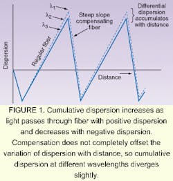
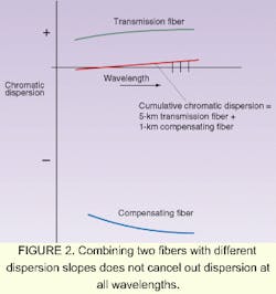
Typically, lengths of compensating fiber are inserted at regular intervals along the transmission line. As a result, the cumulative dispersion increases over some stretches, and then decreases when passing through the compensating fiber (see Fig. 1). In this design, the cumulative dispersion over a fiber system can be zero without incurring four-wave mixing penalties, because the dispersion of any fiber segment is always large enough to keep adjacent optical channels from staying in phase with each other over long distances (the effect that enhances four-wave mixing in zero-dispersion fiber).Dispersion compensation is not perfect for all optical channels transmitted. In this simple example, the cumulative dispersions differ slightly among the channels shown, so the sawtooth patterns slowly diverge. This effect is a consequence of the dispersion slope—the change in dispersion as a function of wavelength. The dispersion slope is often approximated as a straight line, but in reality it curves slightly. In addition, two fibers that can be matched to give zero dispersion at one wavelength may not have complementary slopes; these effects cause a slight residual dispersion over a fiber span (see Fig. 2).
Some systems use three types of fibers per span, which can minimize nonlinear effects as well as help compensate for dispersion. For example, each span between fiber amplifiers in a state-of-the-art submarine cable contains three types of fiber. Large effective-area fiber is used in the part nearest the transmitting amplifier to minimize nonlinear effects. A length of nonzero dispersion-shifted fiber designed for submarine use follows; its zero-dispersion point is shifted to a wavelength longer than the amplifier band used in the fiber. The segment nearest the receiving amplifier is step-index single-mode, which has a high positive dispersion that compensates for the negative dispersion of the nonzero dispersion-shifted fiber. The lengths of each type are chosen so total dispersion of each span is close to zero.
This approach can compensate for dispersion well enough to allow 10-Gbit/s transmission over most operating distances. With the proper choice of fiber, it can provide some compensation for the fiber dispersion slope, although minor differences in dispersion remain. However, more exact compensation is needed over extreme distances or for 40-Gbit/s systems, and needs to be applied to individual channels at the receiver or transmitter. One approach is fabrication of chirped fiber Bragg gratings with sections that reflect different wavelengths, which could be designed to serve as optical delay lines for specific wavelengths, compensating for chromatic dispersion. Another, called the virtual-imaged phase array, uses micro-optics to selectively delay certain wavelengths. A third takes advantage of the high dispersion of higher-order modes in fibers that support extra modes. All three approaches are in development.1
Other complications also arise as transmission systems push against dispersion limits. One is the dependence of chromatic dispersion on fiber temp-erature. For nonzero dispersion-compensated fiber, the effect is only 0.002 ps/nm-km per degree Celsius, but over a 1000-km span that accumulates to 2 ps/nm per degree.2 That poses little problem in submarine cables, because ocean-bottom temperatures are very stable. However, measurements of cables buried a meter underground in Montana showed summer-to-winter variations of 20°C.3 Such large variations can affect transmission over 8000 km at 10 Gbit/s, or over much shorter distances at 40 Gbit/s.
Compensating for those low and variable levels of dispersion will require separate tunable compensators for each optical channel in a system. In these systems, the receiver for each optical channel would monitor dispersion and adjust the tunable compensator through a feedback loop. Various techniques have been demonstrated, including chirped fiber Bragg gratings, virtual-imaged phase arrays, and "all-pass" filters, which include ring resonators. In one experiment, tunable fiber Bragg gratings provided the compensation needed for 160-Gbit/s transmission. Developing practical versions of these tunable compensators is a key requirement for long-distance transmission at 40 Gbit/s.
PMD compensation
Compensating for PMD poses a different set of problems. One component of PMD is intrinsic to the fiber itself; other components are extrinsic, arising from interactions between the fiber and the environment. Extrinsic PMD includes a variable component that responds to changing environmental conditions, and creates a differential group delay that varies randomly over time, like fading effects in radio-frequency transmission. Monitoring experiments confirm the random fluctuations in PMD, which at times can peak at levels high enough to interrupt transmission. One bit of good news is that the higher the peaks are, the faster they decay, so PMD has its highest values only for brief intervals.Polarization-mode dispersion poses no significant problems at 2.5 Gbit/s, but the high levels of intrinsic PMD in some older fibers can create difficulties at 10 Gbit/s. Fiber-production techniques have been changed to reduce intrinsic PMD, so new fibers generally can transmit 10 Gbit/s without significant PMD problems if installed properly.
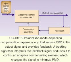
Future 40-Gbit/s systems will require PMD compensation to achieve adequate performance. Several types of compensators have been demonstrated, and at least one is offered commercially. However, their operation is complex. PMD varies continually, so the compensation scheme must be active, with some way of sensing PMD and applying a feedback signal to an adjustable element to reduce the magnitude (see Fig. 3).4
Many variations are possible. The feedback signal may be generated by measuring the degree of polarization, the electrical spectral width of the detected signal, the detected optical power, or by estimating the bit-error rate. This information is used to adjust the compensating elements to minimize PMD effects accordingly. The compensating element combines polarization controllers with components that exhibit a high degree of birefringence to provide time-varying control over the relative delays of different polarizations.
Because of the nature of PMD, compensation is far from perfect. Compensating for so-called "first-order" PMD allows a system to operate with PMD pulse spreading that reaches 28% to 40% of a bit interval. Developers also are working on techniques to counteract high-order PMD effects.
The 40-Gbit/s challenge
Dispersion compensation is among the most crucial technological challenges facing developers of 40-Gbit/s systems. Static compensation suffices for virtually all 10-Gbit/s systems, but 40-Gbit/s transmission will require active systems that continually monitor output signals to provide feedback to the dispersion-compensating elements. The nature of PMD makes it the most difficult challenge, and it may be impossible to control completely. It's possible that 40-Gbit/s transmission may carry some inherent risk of temporary bursts of noise when environmental conditions produce peak PMDposing new challenges to system operators.
REFERENCES
- V. Srikant, OFC 2001 Technical Digest, paper TuH1.
- B. J. Eggleton, OFC 2001 Technical Digest, paper WH1.
- J. Nagel, "Fiber issues for system deployment," OFC 2001 Tutorial.
- D. Penninckx and S. Lanne, OFC Technical Digest, paper TuP1.

Jeff Hecht | Contributing Editor
Jeff Hecht is a regular contributing editor to Laser Focus World and has been covering the laser industry for 35 years. A prolific book author, Jeff's published works include “Understanding Fiber Optics,” “Understanding Lasers,” “The Laser Guidebook,” and “Beam Weapons: The Next Arms Race.” He also has written books on the histories of lasers and fiber optics, including “City of Light: The Story of Fiber Optics,” and “Beam: The Race to Make the Laser.” Find out more at jeffhecht.com.

