Fast-steering mirrors improve active beam stabilization
Beam-stabilization modules based on fast-steering mirrors correct errors in laser-beam alignment and loosen specifications on other components while increasing system robustness.
Phillip V. Mitchell, Peter B. Griffith, and Donald K. Henderson
Once solely a research tool, the laser is now an enabling technology for a wide range of applications in semiconductor manufacturing and inspection, industrial marking, materials processing, biomedical systems, reprographics, information display, and telecommunications. Given today's accelerated product-development schedules, laser-based optical systems are being pushed to produce finer resolution and greater throughput as soon as the application is developed.
To fulfill these expectations, today's laser systems must maintain precise optical alignment in demanding manufacturing environments that run continuously. Vibration or thermal-induced motion can blur precise images, reduce critical intensities, and misalign interfaces between laser and target, leading to severely compromised system performance. While using active and passive vibration isolation, athermalizing the design, and redesigning the mechanical structure can substantially reduce misalignment, none of these approaches is quick, simple, or guaranteed to keep the laser aligned to the optical axis.
Dynamic laser-beam alignment actively reduces misalignment from vibration sources, thermal gradients, and mechanical creep. The success of this approach depends on the fast response characteristics of the active mirrors maintaining the alignment. Originally developed for military and aerospace applications, fast-steering mirrors (FSMs) have recently been commercialized and incorporated as active mirror elements in high-performance beam-stabilization and alignment modules. These modules are a simple, practical approach to system performance improvement.
Sources of laser-beam misalignment
Tilt errors that deviate a laser beam from the intended optical axis originate from three locations: internal to the laser, the optical beam-delivery system, and the external environment. Within the laser, the collimated beam can be subjected to strong thermal gradients, to vibration sources such as fans, shutters and cooling water, and to mechanical creep and aging optics. Tilt-error-generating thermal gradients, mechanical creep, motor vibration, mechanical impulse, and circulating fan turbulence can affect the optical beam-delivery system. External sources of shock and vibration from neighboring production equipment, loading and unloading parts, and environmental changes can drive resonances within the beam-delivery system and the laser. The net impact of all of these factors is to apply a spectrum of vibration to otherwise-static optomechanical components, resulting in a temporally varying misalignment of the laser beam.
Two dynamic parameters measure laser misalignment from the desired optical axis: lateral displacement and angular deviation. Each of these parameters is a function of time and as such can be represented by a temporal trace or by a power spectral density (PSD). The PSD is very useful because it graphically displays the angular misalignment (q2/Hz) as a function of the error frequency. Typical optical systems have PSDs dominated by thermal drifts and low frequency vibrations, while PSD high frequencies are determined by the resonant characteristics of the mechanical mounts. A beam-stabilization module is designed to reduce the input tilt errors or disturbances to a level that renders them meaningless to the functioning optical system. This reduction is verified by taking a PSD of the residual or output tilt error of the module.
Laser-beam stabilization
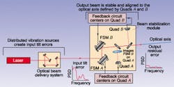
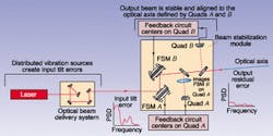
The most common beam-alignment method relies on the use of two mirrors oriented so that two sequential 90° turns leave the beam propagating in the same direction but jogged over to one side (see Fig. 1). During the alignment process, the first mirror is used to set the beam to the desired point at which the surface of the second mirror intersects the desired optical axis. This removes the lateral displacement by forcing the ensemble of distributed tilt sources to appear as if they originated from a single point on the surface of the second mirror. The second mirror is then used to point the beam in the direction of the optical axis, correcting for all angular misalignments.
A beam-stabilization module requires active mirrors controlled by a misalignment detection system.1 Feedback from the detection system is used to continuously realign the beam within the response bandwidth of the active control system. The misalignment detection system consists of two position-sensing detectors (lateral-effect or quadrant) that define the optical axis. The active mirrors are the limiting factor in achieving the bandwidth and dynamic range necessary to reduce the input error to the desired level. By comparing the Bode plots (magnitude and phase vs. frequency) of potential active mirrors with the PSD of the input tilt error, an active mirror can be chosen that will give the beam-stabilization module the best performance. Generally, motor-actuated mirrors are slow; piezo-actuated mirrors are limited in dynamic range; and dual-axis galvanometer mirrors suffer from different pivot points for each axis qx and qy. Fast-steering mirrors (FSMs) are ideal for beam stabilization, having phase and amplitude bandwidths in excess of 300 Hz, dynamic ranges exceeding 6° (optical), and a common pivot point for qx and qy.
Fast-steering mirrors
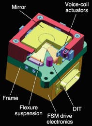
An FSM consists of six important elementsvoice-coil actuators, mirror suspension, internal-position feedback sensors, mirror, drive electronics, and frame (see Fig. 2). Four voice-coil actuators are mounted to the mirror and provide the means to tilt the mirror. Two voice-coils are connected on opposite sides of the mirror and operate as a push-pull pair, rotating about the axis that bisects them. Therefore, two actuator pairs are used to produce two orthogonal rotations (qx, qy). A flexure suspension system is used to support the mirror and allows free rotation about orthogonal axes while constraining piston, side-to-side, and rotation about the normal axis.
Differential impedance transducers (DITs) are included in the assembly to provide internal position feedback when the mirror is not locked to the quad cells. The position feedback from the DITs stabilizes the mirror against unwanted vibrations, ensuring that the laser remains on the quad cells before loop closure. The DITs also provide a home position that the system can reference, should the quad-cell feedback loop be unintentionally broken.
Beam-stabilization module performance
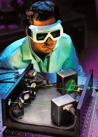
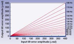
A dynamic beam-stabilization module was developed around two high-performance FSMs (see Fig. 3). Tests were run to determine the residual tilt error for a family of sinusoidal input errors of varying amplitudes produced by a third FSM. In effect, this third FSM was simulating distributed vibrations sources.
For error frequencies up to 70 Hz, a reduction in error amplitude of at least one order of magnitude is expected (see Fig. 4). Even for frequencies as high as 140 Hz, there is a reduction by at least a factor of two. Design engineers can use Fig. 4 to estimate performance improvement of their systems by bounding the input tilt-error magnitude and frequency. If the designer knew that the maximum frequency was 70 Hz and the maximum amplitude was 400 µrad, then the designer could predict that the residual error would never exceed 40 µrad.
The use of an FSM-based beam-stabilization module in laser-based instruments offers the potential to correct large-amplitude long-term drifts and small-amplitude transient errors, to simplify the design tolerances of many precision optical components, and to produce a robust instrument. For example, an FSM-based beam-stabilization module may allow the use of lower-cost optical mounts that have relaxed specifications regarding vibration resistance and long-term drift. In addition, less-stringent attention can be paid to component thermal characteristics. In some instances, the need for vibration-isolation technology can be eliminated.
The introduction of dynamic compensation can enable an existing product to meet higher resolution or stability requirements without any other redesign. Thus, for system developers, the use of automated dynamic beam stabilization can reduce costs by decreasing component count and loosening component specifications. Just as important, it can shorten design-cycle time by simplifying the system design and reducing the need for in-depth modeling and testing of vibration effects.
REFERENCE
- S. Grafstrom et al., Opt. Comm. 65(2), 121 (1988).
PHILLIP V. MITCHELL is manager of technology development, PETER B. GRIFFITH is product manager, and DONALD K. HENDERSON is senior staff optical engineer at Newport Corp., 1791 Deere Ave., Irvine, CA 92606; e-mail: [email protected].
