Membrane mirrors modulate light
Cardinal Warde and H.-H. Ieong
In combination with spatial filters, deformable membrane mirrors can serve either as light shutters or two-dimensional spatial light modulators.Membrane-mirror light-modulator (MLM) technology has been in existence at least since 1968.1 The technology incorporates a deformable membrane mirror as the light-modulating element over either a single electrode as in the shutter configuration, or over an array of addressing electrodes as in the spatial light modulator (SLM) configuration. The advantages of MLM devices include: amplitude or phase modulation of light over a wide (ultraviolet to long-wave infrared) wavelength range, polarization-independent modulation, high optical efficiency, fast (microsecond) rise times, high optical damage threshold, and large-area beam modulation.
Membrane-mirror light modulators and shutters are attractive for applications such as adaptive optics, projection displays, large-area light beam modulation, white-light (broadband) image shuttering, high-speed photography, laser pulse gating, optical printing and engraving, spectroscopy, and optical-signal processing.2,3,4,5
Device description and principles of operation
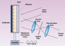
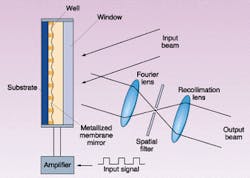
The MLM consists of an electrically or optically addressed substrate that supports a two-dimensional array of pixel wells etched into an insulating layer atop the substrate (see Fig. 1). A thin metal-coated membrane bonded to the insulating layer covers the wells and acts as the deformable mirror. Devices based on pixel well patterns such as one-dimensional line gratings and two-dimensional rectangular and hexagonal grids have been fabricated. A membrane-mirror light shutter (MMLS) uses a single substrate electrode, whereas the SLM employs an array of substrate electrodes. In the SLM configuration, each electrode may address several wells. The metal coating on the membrane acts as the second electrode. This substrate-metallized mirror assembly is sealed in an evacuated housing that is fitted with a readout window.
In operation, voltages applied across the wells by the electrodes electrostatically deform the membrane mirror into the wells. As such, these membrane-mirror light modulators are a class of microelectromechanical systems. Several means of addressing a two-dimensional deformable membrane have been demonstrated, including electron-beam addressing, optical addressing, and electrical addressing via integrated circuits.1, 6-12 Other addressing schemes include discrete electrodes, row-column electrode patterns, thin-film transistor arrays, matrix-addressed electrodes, photoconductors, photodiodes, and phototransistors.
The electronic control unit is a high-voltage, high-bandwidth amplifier that can be fed by a signal/pulse generator. It may also provide a direct-current offset that is necessary for certain modes of operation of the modulator. The spatial filter is either a circular aperture (zero-order pass) or a circular opaque disc (zero-order stop) positioned at the center of the focal plane of the Fourier lens.
Zero-order-pass and zero-order-stop operations
The light to be modulated or chopped (incoherent or coherent, polarized or unpolarized) is nominally collimated before it reaches the modulator. Typically up to 10° full-cone angle of divergence can be tolerated. In the SLM embodiment, when there is no voltage across a particular resolution element, the membrane mirror over that resolution element remains flat and the light reflecting off that portion of the mirror surface maintains its collimation. The Fourier transform lens focuses this light to a single zero-order spot. Because in zero-order-pass operation the Fourier-plane spatial filter is a circular aperture, this spot of light passes through the filter and can be recollimated or converted to an image with a second lens. For zero-order-pass operation, this corresponds to the on state of that resolution element. In this case, essentially all the light reflected from this resolution element is recovered as on-state radiance.
On the other hand, when a voltage waveform is applied to a particular electrode, the resulting electrostatic forces deform the membrane mirror into the associated underlying wells, and the membrane mirror becomes a diffraction grating. As the voltage across the wells increases, the deformation of the membrane-mirror increases, and more and more light from this resolution element is scattered out of the zero order into higher orders leading to lower and lower zero-order output intensity. Thus, gray-scale intensity modulation is achieved. At some specific applied voltage, the zero-order light is extinguished and the off state for this resolution element is achieved. The modulator may be driven with square waves or pulses for binary on/off operation, or with sine waves, triangular waves, or any arbitrary waveform. For nonimaging shutter applications, if a small-diameter readout laser beam is used (for example, 2 to 5 mm) no lenses may be necessary if the zero-order light is sufficiently separated from the higher orders so that the zero-order light can be easily filtered out.
In zero-order-stop operation, the Fourier-plane spatial filter is an opaque disc positioned at the center of the Fourier plane. Clearly, in this mode operation, the output light is off when there is no voltage across the wells. When voltage is applied across the wells, the membrane mirror deforms into the wells and a voltage-dependent portion of the light then diffracts, around the stop, into higher orders. This light is collected by the recollimation/reimaging lens to form the output signal. At the extinction voltage, all of the power is in the nonzero-order light and the fully on state is achieved. The contrast ratio in this mode can be extremely high especially at infrared wavelengths.
Operating voltage
Under the influence of the electrostatic forces, the membrane mirror deforms into the wells with a parabolic profile. The behavior of a circularly bounded, parabolically deflecting pixel is such that the deflection at the center of the pixel (representing maximum deflection) may be modeled by
null
where a is the well diameter, s is the well depth, T is the membrane tension, V is the voltage across the well, and e0 is the permittivity of free space.9 Thus, it is seen that the operating voltage scales as the ratio of well depth to well diameter and as the square root of the membrane tension. Typical extinction voltages for visible light can range from as low as 20 V for 100-µm wells to above 200 V for 10-µm wells. The extinction voltage also increases with increasing wavelength, as expected.
Light modulation characteristics
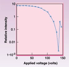
The light modulation of the MMLS can be understood by considering the device as a diffractive reflective surface with a variable phase profile. Thus, Fourier analysis techniques can be used to determine the intensity distribution of the diffracted orders.13,14,15 For a membrane-mirror light-shutter (MMLS) system with one-dimensional (line grating) pixel wells on a 20-µm-well pitch read out at 633 nm, the measured contrast ratio can exceed 1000:1 (see Fig. 2). Note that the zero-order light modulation characteristic is a nonlinear function of voltage. Linear analog responsewhich is required for some analog operationscan be achieved by using lookup table techniques or by amplifying the drive electrical signal with voltage-dependent gain.
Broadband readout
To optimize the contrast ratio for zero-order-pass readout, there must be no overlap between the zero-order and the first-order spots in the Fourier plane so that a simple Fourier-plane aperture can be used to pass only the zero-order light. The modulator can be designed so that this condition is easily met for broadband light. When the modulator is operated with broadband light, to optimize the contrast ratio the diameter of the Fourier-plane spatial filtering aperture or stop should be chosen so that it is large enough to pass (or block) all the zero-order light, but small enough so as to block (or pass) the first-order light. This constraint on separation of the orders becomes more difficult to meet as the collimation of the light is compromised more and more.
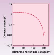
The measured static broadband infrared intensity characteristic of a shutter with a two-dimensional array of wells on a 100-µm pitch in zero-order-pass operation can be plotted (see Fig. 3). The central wavelength of the light is 4.0 µm and the half-width points are at 3.5 and 4.5 µm. The infrared light was obtained by filtering a blackbody source with a long-pass 3.5-µm filter and a short-pass 4.5-µm filter. Note that a contrast ratio of approximately 150:1 is achieved.
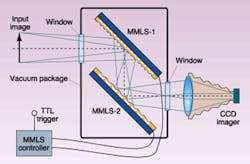
To achieve extremely high contrast ratios (104:1 to 106:1) with laser or broadband light, two or more modulators can be operated in series. In particular, two shutter elements have been packaged into a single cell that has input and output windows to create a broadband high-speed imaging shutter (see Fig. 4). For this application, the device is designed with small wells (about 10-µm pitch for operation at visible wavelengths) so that the zero-order image falls on the detector array and all the higher-order images fall outside the detector array.
Shutter speed
The speed of the MLM is limited by the resonant frequencies of the membrane. Devices with small pixels can be operated at higher frequencies than devices with large pixels, but at the expense of higher operating voltages. For 50-µm-diameter well devices, the resonant frequency is approximately 1 MHz, and for 100-µm-diameter wells it is about 330 kHz.
Square-wave response (shutter operation) up to 1 MHz with minimal ringing has been demonstrated with a shutter using 10-µm diameter pixels. However, for large-pixel, low-frequency (kilohertz) devices, it is often possible to use an offset voltage to increase the effective membrane tension and thereby push the first resonance to a higher frequency. This operation allows higher frequency operation, but at the possible expense of extinction ratio.
The rise and fall times of the modulated light intensity are also two important characteristics. In the zero-order-pass mode, the rise time is the membrane recovery time, since in this readout mode the intensity increases as the membrane recovers from its deformed state to the flat state. The membrane recovery time is dominated by the membrane tension. Conversely, the fall time is the membrane deformation time, and is limited by the rise time of the driving amplifier. The rise and fall time of a 25-µm-pitch device is close to 2 µs. Devices with 50-µm diameter wells typically have rise times of about 5 to 7 µs. Submicrosecond rise times are possible with 10-µm-diameter pixels.
Nonperiodic pulse operation and waveform shaping
The modulator performance is optimal for smooth unipolar drive signals, as smooth waveforms (for example, sine-squared) will minimize membrane ringing. For square-wave and aperiodic pulse operation, and especially for large-pixel (greater than 100-µm diameter) devices, it is often advantageous to round the upper corners of the driving voltage waveform before applying it to the modulator. This is often not a serious compromise, as the intrinsic nonlinearity in intensity-voltage characteristic of the membrane mirror leads to an intensity pulse that is squarer than the rounded driving pulse.
REFERENCES
- K. Preston Jr., Proc. IEEE Inter. Solid State Circ. Conf., New York, 100 (1968).
- C. Warde et al., Proc. SPIE, 3951 (2000).
- K. Preston Jr., Coherent Optical Computers, (McGraw-Hill, New York, 1972), 139.
- K. Hess, R. Dandliker, and R. Thalman, Opt. Eng. 26, 418 (1987).
- J. A. Van Raalte, Appl. Opt. 9, 2225 (1970).
- A. D. Fisher et al., Opt. Eng. 25, 261 (1986).
- T. N. Horsky, Appl. Opt. 31, 3980 (1992).
- L. E. Somers, Advances in Elect. and Electron Physics, 33A, 493 (Academic Press, New York, 1972).
- F. Reizman, Proc. 1969 Electro-optical Systems Design Conf., 225.
- D. R. Pape, Opt. Eng. 24, 107 (1985).
- D. R. Pape and L. J. Hornbeck, Opt. Eng. 22, 675 (1983).
- L. J. Hornbeck, SPIE Critical Reviews 1150, 86 (1989).
- J. D. Gaskill, Linear Systems, Fourier Transforms and Optics, Wiley (1978).
- L. C. Andrews, Special Functions of Mathematics for Engineers, Oxford University Press, 2nd Edition, 237 (1998).
- J. W. Goodman, Introduction to Fourier Optics, McGraw Hill (1968).
CARDINAL WARDE is chairman and H.-H. IEONG is a research scientist at Optron Systems Inc., 3 Preston Court, Bedford, MA 01730; e-mail: [email protected].
