The ideal backlight for a mobile phone would at once be thin, efficient, uniform in illumination properties, and inexpensive to make. Manufacturers are still fishing around for a design that approaches this ideal. Researchers at Nokia Mobile Phones Ltd. (Salo, Finland) and the University of Joensuu (Joensuu, Finland) have developed a diffractive diffuser with properties that vary across its area so that an edge-lit design produces a uniform field of light. The diffusers can be made inexpensively of plastic.
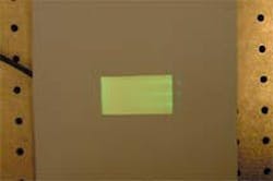
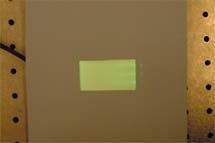
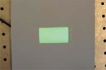
Most diffusers have a structure that is substantially the same across its entire area. Such structures have problems with illumination uniformity when edge-lit: beams of light sent into the backlight from its edges remain visible (see figure). This problem exists whether the backlight is a traditional scattering diffuser or a more efficient diffractive structure. Pursuing diffractive backlighting, the researchers took advantage of the fact that stamps or molds used to fabricate plastic diffractive structures can be patterned using electron-beam lithography—a process that can create very high-precision patterns varying wildly in their makeup across their areas.The perpendicular gratings serve to direct light outward in a conventional manner. The parallel gratings, however, serve to quickly disperse the beams exiting the LEDs within the light-guide layer; because the light is already dispersed far away from the LEDs, there is less need for parallel gratings far from the light emitters. Both gratings have a period of 1.25 µm. Detailed calculations generated the ratio of parallel to perpendicular gratings as a two-dimensional function of position across the backlight; experimental iterations further improved the design. The optimum light-guide thickness is somewhere between 0.8 and 2 mm, according to Markku Kuittinen, one of the researchers.
To make the backlight, a 100-mm photoresist-coated silicon wafer was patterned by electron-beam lithography; the process took close to 40 hours. A 40-nm-thick nickel conductivity layer served as a base on which to grow a 300-µm-thick layer of nickel in a standard electroplating bath. The resulting copy was used to emboss the pixelated pattern into plastic. For large-scale production, the embossing technique would be replaced by plastic injection molding.
The prototype display is 1.8 x 4.1 cm and is illuminated by two LEDs. In the longitudinal direction, the intensity drops by 20% (an amount almost undetectable by the human eye, which is a logarithmic detector); uniformity in the transverse direction is almost perfect. The pixelated pattern permits lighting of the backlight from a single side edge, rather than the typical two opposite edges required for reasonable uniformity. Other pixelated backlights up to 10 cm in length have been fabricated, according to Kuittinen.
About the Author
John Wallace
Senior Technical Editor (1998-2022)
John Wallace was with Laser Focus World for nearly 25 years, retiring in late June 2022. He obtained a bachelor's degree in mechanical engineering and physics at Rutgers University and a master's in optical engineering at the University of Rochester. Before becoming an editor, John worked as an engineer at RCA, Exxon, Eastman Kodak, and GCA Corporation.


