Photonic integrated circuit packaging prototype moves to testing
A butterfly package prototype sample designed by RJR Technologies for photonics technologies and photonic integrated circuits (PICs) applications, in collaboration with the Chip Integration Technology Center (CITC), is being tested in various applications at several European outsourced semiconductor assembly and test (OSAT) providers and R&D centers.
Leveraging existing air-cavity liquid crystal polymer (LCP) technology used in radio-frequency (RF) power package applications, butterfly samples being assembled, uses our air cavity plastic (ACP) design and manufacturing approach, which lowers package costs by 50%, reduces prototype delivery time by 50%, and improves thermal performance by 20% or more compared to traditional Kovar, metal, or ceramic packages.
The solution offers flexibility in geometry and leadframe/heatsink materials and provides near-hermetic package performance. Using the RJR family package design concept, designers can change package input/outputs (I/Os) with relatively short prototype delivery times by changing to a new leadframe spin without incurring large nonrecurring engineering (NRE) tooling charges. We can deliver electrical samples in four to six weeks from receipt of the new leadframe design, as long as the package outline and wall thickness conforms to one of our open tooled packages. Our package solution is designed to handle numerous types of thermal base/heatsink materials and/or metallizations within an existing package design. Thermal base options include copper, copper tungsten, copper molybdenum, super ceramic matrix composite (Super-CMC), and Kovar.
Our packages can be supplied in a single or in-strip format. The in-strip format allows the assembly process to be automated, which enables a lower assembly cost. Also, for the assembly process, we make a fully automatic cassette-to-cassette sealing system that further optimizes costs vs. existing sealing systems used for photonics applications.
Addressing the packaging challenge
Applications using photonic technology, including communications, medical devices, sensors, and optical computing, are poised for a potential breakthrough—but complex and costly packaging technology hampers low-cost, high-volume production. Finding an affordable solution to photonics packaging may be paramount for customers to expand, increase, and obtain new markets at higher profitability. To quote Barwicz et al.: “Cost is more than a commercial consideration. It can define the accessibility of a technology and, in turn, its societal impact.”1
Among the solutions are pluggable optics, heterogeneous integration, and a technology shift from active to passive alignment.
We’re pursuing another viable option: adapting and modifying existing packaging solutions from the semiconductor industry for photonics. In collaboration with CITC, we adapted an existing packaging solution from the semiconductor industry, the near-hermetic ACP packages produced by the injection molding of low-moisture LCP in the “butterfly” layout. The traditional butterfly package is a hermetic metal package often used for photonic applications.2 It is relatively expensive and some of its characteristics, such as hermeticity, are not always necessary.
In 2005, we pioneered the air-cavity RF-power package using LCP injection-molding technology.3, 4 For decades before that, the semiconductor industry had used ceramic packages to provide the benefits of an air-cavity enclosure. The ACP package solution effectively replaced most ceramic packages in the RF power market and other electronic applications requiring an air-cavity package by providing customers with the same electrical and higher thermal performance at reduced package and assembly costs and faster time-to-market.
Air-cavity packaging technology using LCP
Air-cavity packaging is used for high-performance RF and microwave semiconductor components because air, as a dielectric, is lossless compared to the alternative of over-molded packages using lossy epoxy mold compound. Similarly, free-space optical and imaging devices cannot be surrounded by an opaque material that attenuates and/or diffracts light.
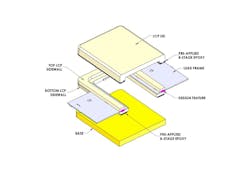
Traditionally, air-cavity packages are assembled using metal-, ceramic-, or epoxy-molded compound materials. The assembly process for molded air-cavity and fully transfer overmold packaging is essentially the same, differing only in how the packages are “sealed.” An overmold package is transfer-molded around an assembled leadframe, and it has no internal cavity. In an air-cavity package, components are assembled into a pre-molded package, which subsequently is sealed with a lid. Our ACP packages use an LCP compound molded around metal leadframes (see Fig. 1).
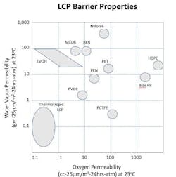
Injection molding processes are a mature technology and take advantage of improvements in molding materials, hardware, controls, high-temperature steels, and mold design software during the past 50 years. Moreover, significant advances in polymer materials that are ideal for the construction and life cycles of electronic packages have been made.5-7 The crystalline domains in the LCP material result in a polymer with minimal water vapor transmission and moisture absorption characteristics (see Fig. 2). A low moisture transmission rate means packages made with LCP are more nearly hermetic than any other type of plastic package. This water vapor permeability rate of LCP is akin to glass.
Its very low water absorption rate ensures that LCP packages do not create problems during solder reflow (at 245°C for a large package or 260°C for a small package) from a sudden vaporization of absorbed moisture that can cause package failures. And its mechanical properties are a nearly ideal balance for electronic packages. This strong and tough, but not brittle thermoplastic is inert and resistant to corrosives and solvents, nonflammable, and contains no halogens. It has proven it can also be used for under-the-hood applications because of its resistance to automotive fluids, such as gas or oil. Since LCP is a thermoplastic material, it can be recycled by regrinding or reused to mold new packages, unlike thermoset epoxy molding compounds.
One of the most attractive properties of LCP is a low CTE that can be tailored. Our solution is manufactured to have a CTE match close to copper, the most common leadframe material for ACP packages. This CTE compatibility results in a matched system that minimizes differential thermal stresses.
A desirable LCP characteristic for injection molding is its lack of adhesion to metals. While this results in clean release from the mold without using contaminating mold release agents, this same property is a negative in the insert-molding process in making the package because LCP does not naturally bond to the leadframe. So, we developed proprietary design features and adhesion promotion solutions to enhance adhesion to the leadframe, which creates a near-hermetic package capable of passing the most stringent semiconductor reliability requirements. In some cases, ACP package designs have passed fine leak testing and/or achieved 200 PPM after 1000 hours of 85/85 testing.
Another element of the ACP package is that it uses B-Staged epoxies to seal the package. We developed a proprietary moisture barrier epoxy that is pre-applied to package lids and sidewalls used to seal packages during the back-end assembly process. These epoxies are solvent-free and meet RoHS and REACH environmental regulation requirements.
ACP packages use metal leadframes to form the conductive elements of a package. Copper is the leadframe material of choice for most package designs, but other materials can be used. Copper is a versatile choice for leadframes, because it features excellent electrical and thermal conductivity at a low cost.
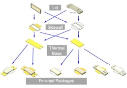
The fourth material used in an ACP package is the thermal base. Unlike ceramic packages that have limitations on the base material choice because of CTE mismatches, ACP package solutions can use different base materials—such as copper tungsten, CPC, copper, and diamond materials. Our epoxies are designed for flexibility to deal with the CTE mismatch when the thermal base is epoxied to the sidewall as opposed to high-temperature brazing, which is very rigid—so if there is a CTE mismatch between the base and package sidewall, it would crack the sidewall (see Fig. 3).
This technology in RF applications is mature and reliable. To date, there have been no field failures reported due to the ACP package, which went into volume production in early 2010 with more than 70 million in use today.
LCP butterfly package for photonics and PICs
Using ACP technology, RJR and CITC designed a butterfly package layout to demonstrate the useability of this concept for photonics and PICs. It is relatively easy to optimize package form, fit, and I/O function for any application, as long as sufficient volume justifies the design and tooling costs. To maximize the applicability and flexibility of our demonstrator package, we made the following design choices:
- A relatively large internal package space measuring 40.2 × 25.0 × 7.85 mm. The outside dimensions of the package are 45.7 × 30.7 × 9.35 mm.
- A leadframe design offering 40-pin DC connectors and 20-pin RF connectors (<30 GHz). Through a relatively easy leadframe design change, a package with 4 × GSG (>60 GHz) pins can be offered (replacing the 20-pin RF) without changing the package (tooling) design. In principle, many other relatively low-cost leadframe designs can be considered, as long as the mechanical interfacing with the package body remains unchanged.
- One optical feedthrough, which includes a mechanical strain relief design. The optical feedthrough is a separate part epoxied into the package during package assembly. Keeping the feedthrough separate created more flexibility; that is, a supplier/manufacturer of fiber blocks/arrays can include this feedthrough in their fiber assembly, which would otherwise not fit. Finally, the section of the package that contains the feedthrough is created using an insert in the injection tooling. Again, through a relatively easy insert design change, the package can also be designed with two optical feedthroughs.
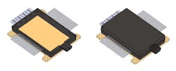
Figure 4 shows the design of the butterfly package, including different leadframes and feedthrough options; this modular approach to creating package flexibility is similar to the configuration flexibility shown in Figure 3. Figure 5 shows real (assembled) prototypes.
In principle, the optical feedthrough creates a fully nonhermetic package. If you want to use the near-hermetic capability that this technology provides, you must seal the optical feedthrough after or during assembly. The moisture barrier epoxy used to seal the lid could also be used to seal the optical feedthrough.
Our design puts half of the feedthrough hole in the sidewall and the other half in the lid. The process is to epoxy the feedthrough to the base during the assembly and align the fiber while the epoxy is curing. Test the alignment and lock it in before the lid is attached, so it is easy to adjust the fiber alignment, which eliminates most of the potential outgassing since the package will be open. Then, seal the package with the lid.
Injection-molded packages have comparatively extensive freedom in geometrical design, which makes it easier and relatively less costly to design variable dimensions and shapes compared to metal package designs. We are currently exploring designs for vertical-cavity surface-emitting lasers (VCSELs) and TOSA/ROSA devices.
Leveraging a proven technology
Overall, our proposed package solution is poised to significantly reduce the costs of individual components for photonics compared to traditional hermetic Kovar, metal, or ceramic packages. Critically, we’ve already proven the effectiveness of this approach in the RF power market with a similar package platform known in the industry as ACP, which rendered ceramic packages obsolete for this market.
REFERENCES
1. T. Barwicz et al., Opt. Fiber Technol., 44, 24–35 (2018).
2. R. Uppal, “Optoelectronics and Photonics Assembly and Packaging Technology,” International Defense Security & Technology (Feb 25, 2023); see https://idstch.com/technology/photonics/optoelectronics-and-photonics-assembly-and-packaging-technology.
3. D. Zyriek, W. Salhuana, and R. Bregante, “Solutions for Low Cost, Near Hermetic Air Cavity Packages,” IMAPS US Device Packaging Conference 2023, Fountain Hills, AZ (Mar. 13-16, 2023).
4. J. W. Roman and R. J. Richard, “A Moisture Resistant Air Cavity Plastic Microwave Power Package Capable of Eutectic Die Attach,” Proc. JEDEX Conf., San Jose, CA (2003).
5. R. Lusignea, “Liquid Crystal Polymers: New Barrier Materials for Packaging,” Packaging Technology (Oct. 1997).
6. R. J. Ross, “New Hydrophobic Materials and Process for Sealing Microwave and Vision Packages,” Proc. Wireless Design Conf., London, U.K. (May 15-17, 2002).
7. R. J. Richard, “Elimination of Moisture in Adhesive Sealed Packages,” Proc. European Conf. Wireless Technol., London, U.K. (Sept. 24-28, 2001).
Marco H. Koelink
Marco H. Koelink is the managing director of Koelink Consultancy, providing consultancy and services to the semicon, photonic, and high-tech industry.
Alexander C.A.J. Dorrestein
Alexander (Sander) C.A.J. Dorrestein is the program manager of Integrated Photonics at the Chip Integration Technology Center (CITC; Nijmegen, Netherlands).
Wil Salhuana
Wil Salhuana is the CEO of RJR Technologies (Hayward, CA).
Raymond Bregante
Raymond Bregante is the cofounder and executive chairman of RJR Technologies (Hayward, CA).


