Optical Fabrication: Magnetorheological finishing is pushed to new extremes
Optical applications that require small, and often concave, glass lenses for precision optical needs continue to multiply in the marketplace. To support these applications, precision surfaces in the optical manufacturing process have grown to include smaller concave-radius substrates including, but not limited to, reference optics and mold manufacturing.1 In many cases, optical grinding and finishing can introduce mid-spatial frequencies (MSFs) that may be difficult to remove.
For small optics manufactured at high volumes, the only practical production technique is molding. In the case of mold manufacturing, many applications such as cell-phone camera lenses may require several small aspheric optics with significant sag or areas of high slope on the surface.2 These molds may also have high-frequency content on their surfaces prior to final finishing. This presents a significant challenge for fabrication. Traditional approaches to polishing these surfaces are not conformal and have a difficult time reaching steeper high-slope areas.
MRF and radius limits
Magnetorheological finishing (MRF), well known in the precision optics industry, is a deterministic, conformal polishing process (see Fig. 1). A workpiece is installed at a fixed distance from a rotating spherical wheel. A magnet located below the wheel surface generates a magnetic field in the gap between the wheel and workpiece. When the MR fluid is delivered to the wheel, it is pulled against the wheel surface by the magnetic field and the act of plunging the workpiece into the ribbon of MR fluid creates a subaperture polishing tool. A sophisticated computer program determines a schedule for varying the position of the workpiece as it sweeps through the polishing zone, in either a spiral or raster path.
MRF tooling has had limits when polishing small, steep, concave surfaces and correcting MSFs. Specifically, two of the main challenges with polishing these surfaces are: providing clearance between the workpiece and the tooling during processing, and spot efficiency when trying to correct MSFs.3
Regarding clearance, the radius of the workpiece must be larger than the radius of the tooling for concave surfaces. This provides the necessary space to avoid unwanted collisions. As the workpiece numerical aperture gets larger, there is also potential for collision between the workpieces and the wheel-support structure, including the drive transmission for the wheel. To satisfy these clearance requirements, a drive belt positioned close to the wheel is one of the best solutions to prevent collisions with steep optics.
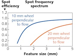
Many surfaces that contain MSF errors created by conventional and subaperture polishing techniques have been limited in MRF correction capability due to the size of the frequency content and efficiency of the spot. The new 10 mm wheel capability now allows for polishing concave optics down to a 7 mm radius of curvature and much higher spot efficiency for MSF corrections (see Fig. 2).Reducing the minimum radius
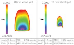
Figure 3 shows a comparison between a representative 20 mm wheel spot and a representative 10 mm wheel spot, both on plano workpieces using a diamond-based fluid. Prior to the development of the 10 mm wheel, it was shown that MRF can correct features as small as approximately 2 mm using optimized process settings.4 This agrees with the calculated spot frequency-spectrum plots shown in Figure 4. The vertical axis in this figure shows the spot efficiency, which is the predicted ability of the spot to make a correction. This plot is achieved by evaluating the 2D Fourier transform of the spot perpendicular to the flow direction (along the width of the spot). By reducing the size of the wheel, the spot size is reduced. The 10 mm spot shows a potential ability to correct features as small as 1 mm in size—half the size of the 20 mm wheel limit.Test data was collected to assess the fidelity of the polishing tool for both a 10 mm polishing wheel and a 20 mm polishing wheel. The tests conducted involved producing, by polishing, a sinusoidal feature of varying frequency from a 3+ mm period down to a 0.8 mm period projected linearly across the optic. The peak-to-valley (PV) amplitude of this feature is 200 nm. The intent of this test is to better understand MRF’s capability to correct MSFs on the order of 0.8 to 2 mm periods.
First, the process around the polishing test that is conducted must be understood. After the removal rate is characterized and a target-removal map has been identified, a solve is conducted. The solve takes the spot and target removal and, through a deconvolution, generates a dwell map—this map is then converted into a tool path that is used by the polishing machine to execute the polishing run. When conducting the solve, many tradeoffs must be made.
As the frequency content of the target removal increases, the spot efficiency decreases and as a result, more-uniform removal is needed to correct these features. Uniform removal consists of a blanket of removal on top of the correction that allows the machine to perform within its dynamic range. For a larger spot to achieve the same root-mean-squared (RMS) removal target, the amount of uniform removal will increase and the polishing time will increase accordingly. It was decided for this test to keep the polishing times similar at about 45 minutes for both the smaller 10 mm spot and the larger 20 mm spot.
The smaller 10 mm run had an RMS removal error target of 6.6 nm with a resulting uniform removal of 167 nm. The larger 20 mm wheel polishing run had an RMS removal error target of 15 nm with a resulting uniform removal of 936 nm. The target RMS was larger than the 10 mm wheel polishing run because the efficiency of the 20 mm spot when trying to correct smaller features is lower, making the spot less efficient. If the target RMS had been reduced to 6.6 nm for the 20 mm wheel run, the run time and uniform removal would have increased significantly. Experience shows that simply adding more uniform removal beyond what is necessary will not only take longer, but will often reduce the overall convergence of the polishing run. For MRF polishing, one of the process heuristics is to keep the uniform removal less than the PV of what is being polished.
The polishing tests described were completed on both the 10 mm wheel and the 20 mm wheel. The same target metrology was used for both polishing tests. For this testing, a commercially available plano optic with a diameter of 25.4 mm was chosen. Full-aperture metrology was used to measure the optic; the equipment used included a 4:1 aperture converter connected to a QED QIS interferometer.
Test analysis
For analysis of the results, a clear aperture of 22 mm was used to reduce any polishing edge effects. In this case, 36 Zernike terms were removed from the resulting metrology, as lower-frequency data was not relevant to the analysis.
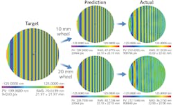
Figure 5 shows the target map, predicted removal, and actual results from polishing for both the 10 and 20 mm wheels. A small reduction in RMS error in the 10 mm wheel prediction and a larger reduction in RMS error in the 20 mm wheel prediction were seen. This is a result of the compromise around target RMS removal error, amount of uniform removal, and time.The actual results clearly show the performance difference of the two polishing wheels. The 10 mm polishing wheel clearly shows the spot’s capability of polishing features down to 0.8 mm, while the 20 mm wheel shows no convergence at those frequencies. Surprisingly, the 20 mm wheel did have a small amount of convergence in the 1 to 2 mm band. What is not shown are the likely adverse effects (higher edge effects and low-order error) of additional removal to get that convergence.
Though the smaller 10 mm wheel provides additional capability, it does come with some process tradeoff. The process engineer will have to consider the benefit of the smaller spot against the lower removal rate and potential increase in polishing time. It may be ideal to focus the work of the 10 mm wheel around frequency content in the 0.5 to 5 mm range, leaving lower-order error correction to larger wheels. In conclusion, the 10 mm wheel provides an additional tool in the process toolbox that can provide solutions to a wide range of applications that were previously unachievable.
REFERENCES
1. C. Hall et al., “New mold manufacturing techniques,” Proc. SPIE, 5868, 58680V (Aug. 18, 2005); https://dx.doi.org/10.1117/12.621097.
2. A. Symmons and M. Schaub, Field Guide to Molded Optics, SPIE Books, eISBN: 9781510601253 and print ISBN13: 9781510601246 (2016); https://dx.doi.org/10.1117/3.2230581.
3. C. Maloney and W. Messner, “Extending magnetorheological finishing to address short radius concave surfaces and mid-spatial frequency errors,” Proc. SPIE, 11175, 111750N (Nov. 15, 2019); https://dx.doi.org/10.1117/12.2536920.
4. C. Maloney, E. S. Oswald, and P. Dumas, “Fine figure correction and other applications using novel MRF fluid designed for ultra-low roughness,” Proc. SPIE, 9633, 96330G (2015); https://dx.doi.org/10.1117/12.2195668.
About the Author
William Messner
Senior Systems Design Engineer, QED Technologies
William Messner is senior systems design engineer at QED Technologies (Rochester, NY).
