3D Surface Metrology: Getting aligned with freeform optics metrology
MERTEN KUNA
For centuries, optical systems were made from spherical and plane optical elements only. Historic images of the first moon landing, tuberculosis bacteria, or of Jupiter’s moons were all made possible without a single asphere or freeform optical element. Since the 21st century, however, the progress of miniaturization has placed new demands on the performance of optical systems, requiring sophisticated laser- and optics-based production and metrology technologies.
Besides aspherical optics that are now a central component of modern cell-phone cameras, more and more freeform optics have found their way into commercial and industrial applications, including the correction of sight defects using toric contact lenses, the spectrometric analysis of exhaust gases with off-axis paraboloids, and heads-up displays using optics represented by non-uniform rational-spline mathematical models, for example.
Independent of these applications, the quality of optical components depends on the performance and compatibility of the metrology systems used in the production process. Here, the metrological analysis of freeform optics becomes especially competitive due to their nonrotationally symmetric shape. To measure freeform optics, Mahr metrology systems use mechanical reference points and 3D positioning systems to eliminate as many degrees of freedom as possible to improve—in a step-by-step process—freeform optics production quality and form-to-fit accuracy.
Establishing fiducials
Mechanical references or physical “fiducial” marks can support the correct mapping of measured point data to the nominal geometry of the desired optical surface. These fiducials play a special role when it comes to mounting, manufacturing, and measuring freeform optics.
For two images showing the very same wallpaper design, for example, the question “which of these pictures has the correct orientation?” cannot be answered correctly without further information (see Fig. 1). But if one of the images contains an additional detail such as a lamp, we are now able to answer the question because we know about the usual orientation of a lamp. This lamp acts as a fiducial to eliminate (in this example) the rotational degree of freedom.
Reducing degrees of freedom
In a 3D measurement, three translational and three rotational degrees of freedom are given. If the algorithm for fitting has too many freedoms, it is possible to compute a wrong result. As a result, reducing the degrees of freedom becomes important when we measure optical surfaces—especially freeforms.
To make the errors of an optical surface visible, we subtract the nominal shape from the measured data. And to accomplish this, the measured data is fitted into the nominal shape to minimize the root-mean-squared (RMS) value of the differential surface.
For any optical surface, a differential result depends on the orientation of the optic while it is being measured. For an optic rotated 0° and 180° between measurements, the differential topography may have the same RMS value (see Fig. 2). However, it is obvious that using the wrong orientational topography to correct the optical surface will aggravate the deviation of the surface instead of improving it. To improve the quality of the fit, it is necessary to lock freedoms—in this case, it would help to lock the rotation around the z axis.3D positioning
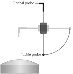
Using mechanical fiducials requires metrology equipment that carefully considers this functionality. The MarForm MFU200 Aspheric system developed by Mahr is equipped with two sensor systems: an interferometric point sensor and an inductive tactile system. In addition, it has several positioning axes and two high-precision linear measurement axes (x and z), as well as a highly accurate rotation axis that is used to automatically spin the sample to record measurement data along concentric circles. On top of this rotational axis, a motorized tip-tilt stage is used for automatic centration and alignment of the optic.
The tactile measurement system can be rotated around 360°, making it possible to swivel the optical sensor and alternate between the optical sensor and the tactile sensor at any time without mounting or unmounting the optical sample (see Fig. 3).Example 1: a toric lens
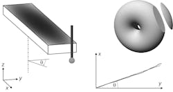
A lens that has two different radii of curvature in the x and y direction is called a toric lens and can be imagined as a slice of a donut (see Fig. 4). For a 3D measurement of this optic, six degrees of freedom are given. But to perform the fit function, we can eliminate three of those by using the outer boundaries of the optic as the mechanical fiducials of the part.First, we eliminate the rotation around z, which is also called C. Therefore, a tactile linear scan is done at the front side of the element. The resulting line delivers information about the current rotational misalignment angle theta, which is then compensated by rotating the part around this angle in the opposite direction.
The next alignment procedure will take care of the centration of the part on the machine using its motorized stage. The centration will be done on the outer boundaries by contacting each side once, detecting the position of the optical element. By knowing the position of the four side surfaces, the part can be centered. This eliminates the freedoms in x and y.
After the alignment, the actual measurement of the optical surface is conducted by measuring 35 circular traces and segments using the interferometric point sensor. This is done by rotating the part using the C axis. Here, the machine operates in active tracking mode, meaning that the vertical axis moves the sensor head up and down to follow the shape of the surface.
From the six freedoms that initially existed, three have been eliminated, allowing the software to compute the correct differential profile and make the surface deviation visible (see Fig. 5).Example 2: an aspheric off-axis toroid
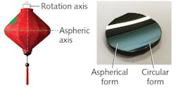
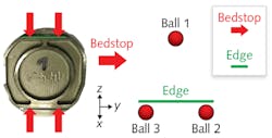
A surface created by rotating an aspheric profile around an axis is called an aspheric toroid. The resulting object can be imagined as a Chinese lantern. If a piece outside the aspheric axis is cut out, the resulting optical element has now a circular form in one direction and an aspheric form in the other where the aspheric axis lies not within the optic’s aperture (see Fig. 6).These elements and the upper linear edge on the part itself are now used to eliminate five degrees of freedom as follows: ball 2 or 3 and the edge determine the position in x; ball 1, 2, and 3 determine the position in z; ball 2 and 3 and the edge determine the rotation around x (called A); ball 2 or 3 and ball 1 determine the rotation around y (called B); and ball 2 or 3 and the edge determine the rotation around z (which is called C).
The position along the y axis is fixed by the bedstop, so this is the only position that is not determined by the balls. To transform the coordinate system of the nominal topography into the machine coordinate system, it is therefore crucial to know the exact position of the three balls. This becomes possible by determining the zenith positions of each of the three balls using the optical sensor. After this is done, the surface of the mirror can then be measured again with concentric circles.
Here, five freedoms have been eliminated to evaluate the measurement. The fit algorithm is only allowed to shift the measured data along the y direction to compute the resulting differential topography. The previously measured positions of the ruby balls are used to shift the coordinate system of the nominal topography into the machine’s coordinate system. The resulting differential topography now contains all deviations of the optical surface itself and the deviation caused by a misplacement of this surface with respect to the mounting edge (see Fig. 8).This resulting differential topography can now be transferred back to the processing machine for correction. The inseparability of the deviation is not important since the resulting error refers to the mounting interface of the part—the final decisive criterium that must be fulfilled so the optical surface is manufactured correctly with respect to the final mounting.
These examples should give an impression of how important fiducials are for the qualification of modern optics. The challenge in this field is the precise alignment of measurement data for the optical surface with the actual optical element. Multisensor measurement systems like the MarForm MFU200 are a promising approach to handling emerging metrology requirements for freeform optics.
Merten Kuna is an applications engineer at Mahr, Jena, Germany; e-mail: [email protected]; www.mahr.com.


