Ray-tracing Software: Structural-thermal-optical performance analysis: The quintessential multiphysics model
Numerical simulation has become an indispensable tool for the design, optimization, and diagnostics of optical systems. A high-fidelity computational model can greatly cut down the amount of time and effort spent on prototyping and related experimental work.
The task of setting up a high-fidelity model becomes more challenging for cameras, telescopes, spectrometers, and similar devices operating in extreme environments. This challenge is perhaps most daunting for optical systems on spacecraft. The environment of space can subject equipment to extreme temperature gradients, from the cold vacuum of space itself to the overwhelming heat of the sun and everything in between.
Changes in temperature directly affect the performance of an optical system because most real-world materials have temperature-dependent refractive indices. In addition, thermal stresses combine with other applied loads to cause deformations that can further degrade performance. Here, we will explore some of the unique challenges of using simulation software for coupled structural-thermal-optical performance (STOP) analysis.
A simple Petzval lens system
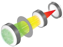
In the example, a Petzval lens system is modeled at uniform temperature and with no applied forces. The Petzval lens consists of front and rear lens groups followed by a field-flattening lens. As seen in Figure 1, collimated rays propagate from the left (green) towards an image plane at the right (red). Also shown are the image plane and an aperture stop between the lens groups.
Now, suppose this simple lens system is inserted into a real-world assembly with stresses and temperature gradients. To perform an accurate STOP analysis, not only must the lenses themselves be modeled, but also the surrounding apparatus. This requires the following questions to be considered:
- How are the lenses mounted?
- What are the boundary conditions for the structural analysis?
- What are the boundary conditions on temperature?
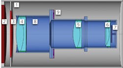
The entire barrel is contained within the thermal shroud boundaries (1), which are, in this example, held at a low fixed temperature of -50°C, perhaps by pumping a liquefied gas through the walls. Radiation then enters the thermal shroud through an exterior vacuum window (2) and additional thermal window (3). This extra thermal window is in place to help regulate the temperature gradient in the lenses. The ambient surroundings outside the thermal shroud are at the laboratory temperature of 25°C.
Also shown are the lens groups (4, 5, and 6), the image plane (7), barrel (8), and a rigid support (9) where the displacement is assumed to be zero. The quantities being solved for include the temperature throughout the lenses, barrel, and windows; the structural displacement in the lenses and barrel; and the ray paths through the system.
STOP analysis requires a combination of numerical methods
From a mathematical point of view, STOP analysis is uniquely challenging because the structural and thermal models require a different type of numerical approach compared to the optical model. The most flexible approach to structural and thermal simulation is the finite element method (FEM). This method involves representing the geometry as a number of discrete numerical cells, or elements, and then approximating the strain and temperature in each element as piecewise functions defined on that element.
The optical performance is best predicted using a ray tracing approach. This is because FEM implementations of optical simulation usually require a mesh fine enough to resolve individual wavelengths, and this requirement isn’t practical for optical frequencies.
If the structural and thermal simulations are performed on a discretized representation of the geometry using FEM, and the optical simulation uses a ray tracing approach, how can the effect of structural deformation and temperature change on the optical performance be factored in? The COMSOL Multiphysics simulation software provides a seamless integration of these different numerical methods within an all-encompassing user interface, which also includes tools for geometry setup, meshing, solvers, postprocessing, and much more. The newest version of COMSOL Multiphysics, version 5.4, includes dedicated tools for coupled STOP analysis and several new examples.
Assumptions for thermal simulation
The radiation entering through the vacuum window and thermal window has a broad spectral range. At visible optical frequencies, it is assumed that light gets refracted by the lens—but in the infrared regime, it is assumed that the lenses are opaque, meaning that they absorb the incoming radiation and then reemit it diffusely in all directions. Therefore, the radiation entering the chamber actually requires two different modeling approaches to be used in tandem. In the optical regime, ray tracing is used to observe the focusing behavior, while in the infrared regime, the thermal radiation is modeled in tandem with conductive transport through the lenses and barrel assembly.
Using multiphysics simulation, the most accurate way to model thermal radiation (assuming ideal diffuse surfaces) is with the radiosity method. Thus, the thermal model combines the radiosity method to model surface-to-surface radiation with the finite element method to model conductive transport through solid bodies. There is no convective transport to worry about because the lenses and barrel are in a vacuum.
Ray tracing in a deformed geometry
The ray tracing algorithm automatically accounts for thermo-optic dispersion and optical stress. The rays interact with a mesh representation of the boundaries in a geometry rather than their analytic representation, and this makes it very convenient to model reflection and refraction by a deformed geometry because the displacement field in each boundary element is known from the FEM simulation. In other words, the same mesh is used to assign degrees of freedom in a FEM calculation of the structural displacement and temperature, and to query the position and normal direction at ray-boundary interactions.
To account for thermo-optic dispersion, the rays can query the temperature field at any location within a lens. This temperature and the ray’s vacuum wavelength are used to compute the refractive index encountered by each ray.
Altogether, multiphysics modeling enables the following to be done simultaneously:
- Model conductive heat transfer and structural deformation using FEM,
- Model radiative heat transfer between diffuse gray bodies using the radiosity method, and
- Trace light rays through the heated and deformed lens system.
Thermal simulation results
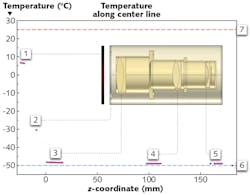
The results of the thermal model demonstrate the importance of using an additional thermal window to regulate temperature in the Petzval lens assembly. Figure 3 shows the temperature in a cross-section of the lenses, barrel, and thermal shroud. Because the temperature change within the barrel is rather hard to see, the temperature is also plotted as a 1D graph along the center line of the assembly.This aptly demonstrates the need for a thermal window—without it, the temperature difference among the lens groups might be as high as 20°C, rather than 2°C, leading to significantly greater thermal stress. This is similar to the rationale behind using double-pane windows for room insulation.
Ray tracing results
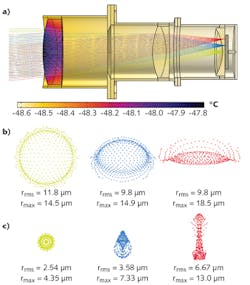
Rays were traced through the thermally deformed system for three different field angles. The trajectories are shown in Figure 4; the temperature field in the lenses and barrel is also shown.From the spot diagrams, it is more obvious that the temperature change has a significant effect on optical performance. Not only are the spots visibly different, but their root mean square (RMS) spot sizes differ significantly.
Looking forward
Using multiphysics simulation, a coupled STOP analysis can be done within a single self-contained, simulation software package. Furthermore, the means for deploying numerical models to a larger user base have improved rapidly in recent years. The democratization of simulation, together with the ease-of-use of modern STOP analysis tools, suggests that the use of simulation in optical design will only become more essential and more widespread in the future.
About the Author
Christopher Boucher
Lead Developer
Christopher Boucher is a lead developer at COMSOL. He received his BS degree in aerospace engineering and physics from Worcester Polytechnic Institute (WPI) before joining COMSOL in 2012.
