Full-wave multiphysics simulation of optical fibers
Optical fibers, which form the backbone of the internet and other digital networks, are one of the most important parts of modern communications infrastructure. They’re indispensable for industrial and medical applications, such as laser cutting, laser marking of parts and products, and laser tumor ablation.
Optical fibers consist of a core and a cladding, but despite their simple structure, they’re not as simple as they appear. The light source for fibers is almost always a laser, which is usually linearly polarized in a certain orientation. Polarization optics such as wave plates, Pockels cells, Faraday isolators, and Brewster windows are used to maneuver the laser beam in various ways.
Imperfections common to optical fibers cause unintentional and undesired polarization rotation in an unpredictable way, which leads to power loss during the laser beam delivery through these polarization optics. For example, optical materials have a slight birefringence, which means it has different refractive indices in different directions. In addition, the fiber core may be slightly elliptical or tapered because of manufacturing limitations, or it can be bent when used. With complexities like these, full-wave multiphysics simulations are necessary when developing optical fibers.
Fiber simulations
When simulating optical fibers, performing a 2D eigenmode analysis for the fiber cross-section is typically the first step. With this type of analysis, one can predict which eigenmodes may exist in the fiber under given conditions. The exit mode will most likely not be the same as the input mode due to the polarization phenomenon. 3D simulations are needed to gain a better understanding of how the mode propagates over the length of a fiber.
Several approaches exist to predict such propagation with 3D simulation, including the beam propagation method (BPM). The BPM is valuable because numerically it’s relatively light, but it uses approximations to Maxwell’s equations and usually solves for a scalar field, even though light is a vector field; any phenomena that require a vector field description cannot be simulated using this method. There are vectorial BPMs, but they still use approximations and are numerically expensive and not easy to use.
Alternatively, the Wave Optics Module, an add-on to the COMSOL Multiphysics software, has the capability to solve Maxwell’s equations with the beam envelope method.1 This is a finite-element-based method that can handle extended optical components rigorously in 3D without an excessively fine finite element mesh or any theoretical approximation, provided a certain condition is met: that the direction of propagation, represented by the wave vector, is known a priori with reasonable accuracy. An optical fiber satisfies this condition because the mode field is guided by the refractive index difference in the fiber, which is geometrically predetermined to give a direction of propagation along the fiber’s extension. Before carrying out the full 3D simulation, the beam’s shape in the cross-sectional direction at the excitation and exit boundaries needs to be determined. For this purpose, boundary mode analysis is numerically carried out for each of the excitation and exit boundaries.
Also known as a transverse mode analysis, boundary mode analysis can compute the vector-valued mode shape on the boundaries and includes all the components of the electric and magnetic fields. Once this is done and the transverse wave number calculated, the propagation constant is analytically calculated and used as an input parameter for the 3D simulation. In many cases, the computation is relatively light, even for long fibers, owing to the efficiency of the beam envelope method and well-matching characteristics of optical fibers.
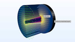
Figure 1 demonstrates an exaggerated case of a technical problem in which the core of an optical fiber is tapered and the initial linear polarization is rotating as the mode field propagates along the fiber. This simulation was performed using a dedicated beam envelope method interface in the Wave Optics Module. The polarization rotation phenomenon cannot be understood with scalar approximations, but is purely vector-valued in nature due to the interaction between the laser’s electric field and the material of the optical components. Therefore, a full-wave simulation is needed to analyze optical fibers.
Polarization-maintaining fibers
In an isotropic optical fiber, the lowest order modes are two-fold degenerate. That is, two orthogonal linearly polarized modes can exist due to the cross-section having circular symmetry. There is no mechanism that prevents one polarization mode of the two degenerated modes from coupling into the other polarization mode in an isotropic optical fiber. Any small deviation from the material’s isotropy or circular symmetry can cause the polarization modes to couple. In real optical fibers, due to manufacturing imperfections or the intrinsic material birefringence, polarization coupling is inevitable during propagation. The tiniest amount of coupling accumulates to a significant amount as the beam propagates over a long distance, rotating the polarization plane in an ordinary optical fiber.
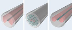
To alleviate polarization rotation, a polarization-maintaining (PM) fiber was developed. In PM fibers, a large birefringence is intentionally introduced. In this situation, the circular symmetry is lost and an exclusive polarization along a preferentially chosen axis can be realized. Common PM fibers include bow-tie, photonic-crystal, and PANDA fibers (see Fig. 2). PANDA and photonic-crystal fibers are widely used for telecommunications, and bow-tie fibers are often used for sensor applications, such as torsion sensors and gyroscope sensors.How can an intentional large birefringence be added? To start, PM fibers are prepared with a core rod, sandwiched by two stress rods in a cladding rod, and then pulled into a designed fiber size under high temperature. Once cooled down, the stress rods have a residual mechanical stress due to the contrast in coefficient of thermal expansion. For this purpose, the stress rods are typically doped with boron trioxide (B2O3). The mechanical stress changes the refractive indices of the fiber materials in an anisotropic way because of the lack of symmetry. The axis along the line with which the stress rods are aligned is called the slow axis; the other is called the fast axis. An exclusive polarization is formed along the slow axis when the residual mechanical stress is present.
Multiphysics simulation of PM fibers
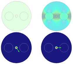
Designing, characterizing, and predicting the performance of PM fibers requires the of use multiphysics simulations, in which heat and mechanical examination can be solved together with eigenmode analyses as well as vectorial electromagnetic simulation. This type of modeling and analysis can be difficult, but systems such as COMSOL’s finite-element-based multiphysics software allow optical fiber designers to combine virtually any physics and solve them together, easily model anisotropic material properties that depend on variables solved for in other physics, and leverage the powerful beam envelope method, which makes optical fiber simulations very efficient.Figure 3 shows the result of 2.5D boundary mode analysis that compares cases with and without a mechanical stress.
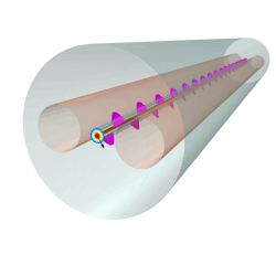
When characterizing a PM fiber, a field polarized within a plane between the two polarization axes can be excited to measure the beat length. The beat length of typical PM fibers is in the order of millimeters, which is much shorter than that of ordinary fibers. Figure 4 shows a 3D full-wave simulation of a PANDA fiber with a linear polarization at 45 degrees, which results in a circular polarization.The efficient beam envelope method for optical fiber simulations enables 3D simulation of long fiber sections. By using this method in combination with multiphysics simulations that include thermal expansion and mechanical stress, and which account for anisotropic material properties, birefringence effects can be analyzed.
REFERENCE
1. B. Sjodin, Laser Focus World, 53, 11, 42-45 (Nov. 2017); www.laserfocusworld.com/16548112.
Yosuke Mizuyama | Principal Engineer, COMSOL and Managing Director, COMSOL GK
Yosuke Mizuyama is formerly a principal engineer at COMSOL (Burlington, MA) and is now managing director at COMSOL GK (Tokyo, Japan).


