Active alignment process reduces fiber-core offsets
Active alignment process reduces fiber-core offsets
Optical monitoring and specialized tools allow assemblers to center fiber core to submicron tolerances.
Mark Graf
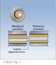
Fiberoptic connectors form a remateable connection be tween two fibers, generally by physically aligning the cores of the fibers with one another. The primary measure of connector performance is insertion loss, usually as tested against an "ideal" reference connector. Conventional connectors consist of a cylindrical ferrule with a precision-honed hole into which the fiber is fixed with epoxy. During the connecting process, the ferrules are aligned in a sleeve; if the fiber cores lie on the respective ferrule axes, then ferrule alignment yields core alignment. Lateral alignment error results when fiber cores are eccentric with respect to the ferrules. This is the most significant contributor to insertion loss in single-mode connectors.
Core eccentricity stems from three sources: core-to-cladding eccentricity, ferrule-fiber-hole to ferrule-outer-diameter eccentricity, or fiber-hole-diameter to cladding-diameter mismatch (see Fig. 1). Fiber manufacturers typically specify a maximum core-to-cladding offset of 1 to 2 µm, and ferrule manufacturers generally ensure a maximum eccentricity of 1 to 2 µm; assemblers attaching connectors to fiber termini have no control over these two parameters. They can control fiber-to-ferrule-aperture mismatch by choosing the fiber hole diameter to match that of the cladding.
This matching process is critical to connector performance. If the hole diameter is too large, the fiber position (and thus the core position) cannot be controlled. Furthermore, a fiber fixed in a ferrule with a large ring of epoxy is positionally less stable and more susceptible to pistoning during temperature cycling. Hole-size selection is accomplished by inserting the stripped fiber into ferrules with successively smaller holes until the smallest hole that can accept the fiber is found. For 125-µm fiber, cladding diameter can vary by ۬ µm; to facilitate assembly, connector manufacturers typically drill fiber holes 1 or 2 µm larger than the nominal cladding diameter.
The hole diameter itself is also subject to manufacturing tolerances. As a result, manufacturers sort their ferrules by hole size, requiring the assembler to maintain a sorted supply of ferrules to accommodate cladding-diameter variations. Matching hole diameter to fiber-cladding diameter is tedious and time-consuming, and this critical step is often not given the attention it requires.
Successful termination with conventional connectors is dependent upon a number of factors over which the assembler has no control. Often errors will cancel each other, yielding acceptable results. The only way to be certain, however, is to measure the terminated connector against a reference model. If it does not yield the desired performance, it must be cut off and the whole process repeated. It is important to remember that even when a connector demonstrates a good match with a reference fiber, there is no guarantee that the connector will perform well when mated with a nonreference device in the field.
Active core alignment
An alternative termination method developed by Diamond SA (Losone, Switzerland) actively positions the core in the exact ferrule center rather than leaving centering to chance. Instead of a one-piece "monoblock" ferrule design, Diamond manufactures a two-component element composed of a hard outer casing (tungsten carbide or zirconia ceramic) and a malleable, copper-nickel alloy insert. The ferrules are precision ground and polished to a dimensional tolerance of 0.5 µm or less.
Rather than attempting to match the hole size to the fiber diameter, ferrule bores are intentionally overdrilled; typical hole size for 125-µm fiber, for example, is 130 µm. A single ferrule type can thus be used with all fibers of a given nominal cladding diameter, eliminating the critical and time-consuming step of selecting the best hole size and the need to sort ferrules by hole diameters.
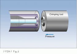
The active core-alignment termination process is initially similar to that used with conventional connectors. The fiber is stripped, cleaned, and then inserted into the ferrule with epoxy. However, in the active core-alignment termination process, before the epoxy cures, a circular crimping tool with a wedge profile is used to plastically deform the copper-nickel alloy surrounding the fiber (see Fig. 2). The tool closes the hole to match the fiber cladding and leaves a circular impression on the ferrule end face. This process moves the fiber into the center of the ferrule with an eccentricity of 2 µm or less, sufficient for multimode terminations. After the epoxy fully cures, the connector can be polished and assembled.
Alignment for single-mode terminations
To ensure consistent performance, single-mode connectors must meet tighter eccentricity specifications than multimode connectors. Enhanced active core alignment using a second crimping instrument from Diamond can reduce eccentricity to 0.25 µm or less.
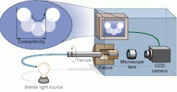
The fiber is installed in the ferrule using the same process as for multimode fiber. After the expoxy cures, the assemblers cleave and polish the fiber, then mount the ferrule in the Z-276 crimping instrument. Visible light from an incoherent source is launched into the opposite end of the fiber (see figure on p. 125). A charge-coupled-device (CCD) camera captures the light exiting the fiber, displaying it on a video monitor as a point image. When the ferrule is rotated, a core-to-ferrule decentration causes the image to describe a circle with diameter equal to the concentricity error (twice the eccentricity). Two calibrated marker lines on the monitor permit the operator to quantify any error.
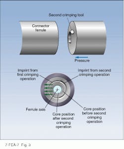
Eccentricities greater than 0.25 µm can be corrected in a second crimping step using an arc-shaped tool with a wedge profile. Subtending only 120° of arc rather than a full circle, the tool can selectively deform the alloy on one side of the ferrule, nudging the fiber into place (see Fig. 3). The CCD-camera/ video system allows the assembler to monitor the core position as the fiber aligns to the ferrule axis. When tool pressure is released, the alloy remains plastically deformed; when the ferrule is rotated, the point image should now remain stationary.
The precise positioning offered by the active core-alignment process yields enhanced performance between any two randomly mated connector pairs. As compared to the conventional matching process, alignment is not left to chance. In addition, it is reasonably quick and eliminates the need to maintain a supply of carefully sorted ferrules to accommodate variations in cladding diameter. The contact between the deformable alloy and the fiber after crimping ensures positional stability, reducing pistoning and increasing thermal stability. The process results in very little scrap or rework. Connectors terminated with this process are fully compatible with connectors from other manufacturers. o
Optical inspection system quantifies fiber-core decentration in real time; specialized crimping tool allows assemblers to correct fiber position.
FIGURE 1. Eccentricities introduced during the manufacture of optical fiber and ferrules, as well as during connector assembly, can introduce lateral alignment errors that cause signal loss.
FIGURE 2. Wedge-shaped crimping tool deforms soft metal ferrule insert to hold fiber in place, centering it to within 2 µm.
FIGURE 3. Wedge-shaped arc selectively deforms one side of the ferrule insert to nudge fiber into place with an error of less than 0.25 µm.


