Water-guided lasers create clean cuts
JOHN MANLEY, ROY HOUSH, FRANK WAGNER, and BERNOLD RICHERZHAGEN
In 1993, scientists at the Institute of Applied Optics of the Swiss Federal Institute of Technology in Lausanne succeeded in creating a laser light-guiding water jet. Called the Laser-Microjet (LMJ) by its inventors, the technology has since proven its efficiency and reliability in many materials-processing applications, especially in the semiconductor and microelectronics industries. Indeed, the water-jet-guided laser boasts indisputable advantages over classical alternatives for numerous materials-processing applications.
Originally the water-jet-guided laser was developed to reduce the heat-affected zone (HAZ) near the cut. However, the use of a water jet instead of an assist gas stream, which is typically applied in conventional laser cutting, led to several additional benefits.1 The absence of beam divergence due to the light guidance by the jet, for example, is an advantage when cutting materials thicker than 1 mm. The immediate cooling of the cut is realized by coupling a pulsed laser in a continuous water jet. The heat extraction of the thermal load in the material occurs between laser pulses when only the water jet is in contact with the cutting surface. The high momentum of the water jet efficiently expels the molten material, enabling a burr-free, clean cut. Furthermore, the water layer on the sample cools any droplets of substrate material and inhibits their recast to the substrate.
System basics
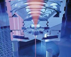
The water-jet-guided laser is based on a stable water jet produced by using a high-quality diamond or sapphire nozzle. To create the jet, a constant pressure pump feeds a pressurized chamber (50 to 500 bars) with water. Pure degassed and filtered deionized water is used to minimize light absorption within the water, thus eliminating potential pressure or velocity-profile perturbations in the nozzle, both of which would destabilize the jet.
The most rudimentary optical setup for coupling light into the water jet would be to focus a laser beam through a window into the nozzle, very similar to a typical fiber-coupling setup (see Fig.1). Using this scheme, however, results in low-intensity wings on the nozzle border and high-intensities on the optical axis. Therefore, we use a fiber-coupled laser with the output from the fiber projecting into the nozzle with varying demagnification. Typically the fiber is a step-index type of 200-µm core diameter. We take advantage of the nearly flattop, near-field profile at the fiber output in two ways. First, we avoid high intensities of light in the water to minimize any nonlinear interaction between water and light. Second, the sharp edge of the image allows the light intensity on the sensitive nozzle border to be minimized. High light intensities contacting the edge of the nozzle will destroy it; hence, the laser alignment and the nozzle position is done at low light intensity with an alignment imaging setup.
Use of a fiber-coupled laser also allows the flexible "plug-and-play" exchange of different lasers and the ability to easily adapt the system to a particular production environment. The lasers used are either flashlamp-pumped Nd:YAG systems with pulse durations of less than 120 µs or multimode Q-switched devices emitting at 1064, 532, and 355 nm.
Once the light has been injected into the water jet, it is reflected at the water-air interface due to the refractive-index step. The light-guiding properties of the water jet are identical to those of a multimode optical fiber with very high NA, including effects such as modal noise in the near-field intensity distribution.2
Substrates are fixed onto an x-stage and the optical setup is implemented in an "optical head" mounted on a y-stage. Both x and y stages use high-precision linear drives allowing for high-speed translation with ±3-µm positioning precision. The z-variation of the stage is required only for adapting the system to different working distances created by various nozzle sizes and water pressures and is irrelevent during the cutting procedure.
The LMJ combines the output of a powerful Nd:YAG laser with the relatively gentle low-pressure water jet and as a result is particularly suited to applications in which the fragility of the material or its extreme hardness complicates machining using other methods. Although many industries—including automotive production, medical device manufacture, electronics, machine tools, and solar energy—are using the system, we will discuss several microelectronics applications to demonstrate how the LMJ facilitates process optimization.
Semiconductor processing
Die separation, one of the last operations in the transformation of silicon wafers into chips, requires fast and sure separation. The use of the water jet rather than assist gas allows one-step cutting of silicon chips and offers the advantages of the absence of surface debris and efficient cooling of the material. The gentleness of LMJ processing ensures that cracking, chipping, and burring are avoided. Wafers as thin as 50 µm can be cut with the LMJ at up to 200 mm/s with excellent cut quality and a kerf width as low as 28 µm.
In another example, the production of thin wafers is based on standard wafers with rounded edges that are thinned from the backside by mechanical grinding followed by chemical polishing. At the end of the thinning process a very sharp edge remains. The strong shearing force during the grinding creates many microcracks at the wafer edge. Propagation of these cracks will occur with the slightest thermal or mechanical stress applied to the thin wafer, leading to wafer breakage. To avoid breakage, the wafer edges must be treated to allow handling of the thin wafer; this is accomplished by ablation of the zones with microcracks on the wafer edge.
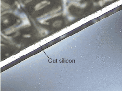
While seemingly simple, the requirements for the cutting process are quite demanding. The process must induce no mechanical strain to the thin wafer or additional breakage will occur during the cutting process. In addition, the cutting technology must not induce new microcracks, be fully automatic from cassette to cassette, and be capable of precisely following the outline of the wafer. The LMJ system is able to make this cut, leaving a clean edge on the thin wafer with no new microcracks (see Fig. 2).Furthermore, the LMJ is sufficiently flexible to ensure that all wafer diameters, wafer shapes, and a variety of thicknesses can be handled. Substantial yield improvements have been achieved because wafer losses due to cracking are reduced to zero.
Stencils and masks
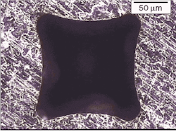
Solder mask stencils are metal or plastic perforated sheets used to apply solder paste to land locations on a circuit board where the paste will be reflowed to attached electronic components (see Fig. 3). These stencils are used for the application of screen-printing solder paste or conductive adhesives onto the boards. Laser-cut stencils are typically used for applying paste to boards containing fine pitch components.A large number of small apertures must be drilled in the metal or plastic sheet. Precision, quality, and speed are critical. In conventional production, the apertures are made by punching, milling, etching, or laser cutting. Laser cutting has the advantage of flexibility and speed while being able to cut very small apertures. Conventional laser cutting requires post-treatment to clean the stencil and deburr the backside. With a water-jet laser system, the continuous water jet immediately recools the cut between laser pulses, resulting in a very slight depth of thermal penetration and a very narrow, parallel, burr-free, virtually clean cut free of thermal damage.
Hard materials
Super-hard materials, such as carbon boron nitride (CBN), silicon nitride (SiN), and synthetic diamond, are commonly used as cutting tools for, boring, drilling, milling, threading, and grooving. The extremely hard, brittle, and abrasive nature of ceramics has required the use of diamond wheels and large amounts of liquid coolant for machining operations. Diamond-wheel sawing is slow and tool-consuming, and very thin gaps cannot be made. Electrodischarge machining works only with electrically conductive materials, which excludes pure CBN, diamond, or SiN. Drilling CBN is possible, but only on a very limited basis and while conventional laser cutting is possible, thermal damage occurs and the edges must be post-processed, among other problems.
Test trials have shown excellent absorption of IR radiation in CBN and SiN, proving the water-jet-guided laser system works well. Because of its low IR absorption, synthetic diamond has to be cut with a short-pulse laser. The water jet guides laser energy to the bottom of the cut, enabling parallel, very narrow slits to be fabricated while the water jet prevents thermal damage. In addition, cutting time is short (within seconds) and tolerances are better than those obtained with conventional processes. During operation, the laser moves rapidly back and forth until the material is through-cut.
The water-jet-guided laser has enhanced or made possible numerous materials-processing applications and in many cases has demonstrated better results than conventional alternatives, especially when working with heat- or stress-sensitive materials. Even after 10 years of development, the technique continues to find new applications in a diverse range of markets.
REFERENCES
- B. Richerzhagen, Entwicklung und Konstruktion eines Systems zur Übertragung von Laserenergie für die Laserzahnbehandlung, doctoral thesis, EPFL (1993).
- P. Couty, F. Wagner and P. Hoffmann: J. Opt. Eng., submitted (2004).
John Manley is manager of Synova USA (Phoenix, AZ). Roy Housh is international sales manager, Frank Wagner is R&D process manager, and Bernold Richerzhagen is president and CEO at Synova SA, Ecublens, Switzerland; e-mail: [email protected].


