Motion-control systems gain flexibility
WARREN BOOTH
Precision motion-control—or precision-positioning—components are now essential parts of the complex and intricate pieces of equipment used in many high-technology industries, including semiconductor, computer mass storage, and electronics manufacturing. These applications require complex motion, submicron positioning resolution, and a high degree of both position repeatability and accuracy. The motion may occur along a linear axis, a rotary axis, or any combination of linear and rotary axes. The user may want to control the interaction between multiple movements, along multiple axes, and between several stages that could all be in motion simultaneously.
However intricate the movements, the components, and their interactions, it is now possible to design, select, install, and operate components of a positioning system more easily than ever before. An understanding of how the motion-control industry previously solved engineers' positioning applications makes clear the benefits that current solutions provide.
The three major elements in a typical motion-control positioning system include the component that moves (usually a translation or rotary stage), the motor driver card, and the motion controller. Historically, the primary user of such a system was a researcher who would obtain each of the three elements from a different source, then integrate them to create a system that provided the desired movement for the application.
Barriers to successful integration were great. The connectors or pinouts for each device were not compatible across manufacturers so jumper boxes (with anywhere from six to ten soldered joins per connector) had to be used to make the motion-controller and motor-driver electronics compatible. Each type of motor required a different driver card. A vendor might have to maintain two dozen different driver cards to support just the stepper motors used for a particular stage. If the vendor supported multiple types of motors for many types of stages, then inventory was proportionately larger and the possibility for incompatibility increased. The penalty for a mismatch was damage to or destruction of either the card or the motor, or sometimes both.
The controller module also caused difficulties, due to incompatibilities between software and hardware. Software limitations were primarily because the motion controller operated in DOS or Windows 3.1 environment. This extended the software development cycle time and reduced flexibility. Software was not standardized and required users to acquire motion-control expertise in programming language. Furthermore, programmers didn't have a good method of programming motion in commonly acceptable units such as microns; instead they measured the motion in "steps" or counts that required conversion into the appropriate physical units, as well as a different conversion for each pitch of lead screw. Hardware also was not standardized or easy to access or maintain. Many tools might be required to install a card in the controller. Each axis had to be identified and electrically configured for the stage motor. Essentially, users had to become experts in positioning equipment before they could continue with the primary work they had intended to perform.
Changes in the greater environment
Computing improvements and inventions have come together at an opportune time to allow manufacturers of motion-control systems to make major improvements in the systems they offer to customers. The first improvement was making microprocessors smaller and less expensive so that they could be integrated into the controllers as well as the motor drivers and stages, thus putting programmable intelligence directly on the motion platform.
A second improvement is the move from ISA (international standard architecture) and EISA (extended international standard architecture) bus connections to 32-bit-compatible, PCI (peripheral component interconnect) bus connections. Today's new data standards allow full 32-bit programming and video-capable data exchange rates between the motion controller and the computer. Another change includes the industry's move to Windows 95/NT as a more universal platform, allowing for ease of programming and ease of integration (see Laser Focus World, Jan. 1997, p. 135).
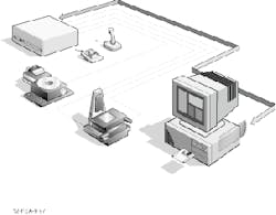
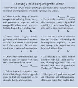
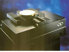
Companies in the motion-control business have implemented many of these changes, resulting in systems that are easier to install, easier to use, and more appropriate for commercial operating environments (see "Choosing a positioning-equipment vendor," below). For example, Newport Corp. has developed a new precision motion-control product family that can provide a complete system solution for any customer.The stage. A typical motion-control positioning system includes a stage, a motor driver card, and a motion controller (see Fig. 1, top of this page). The stage is the part of the system that actually provides physical movement. The most important step after building a reliable stage is to put intelligence, in the form of an EPROM (erasable programmable read-only memory chip), on the stage. The nonvolatile EPROM can be preprogrammed with necessary information unique to the stage—its electrical characteristics, motor type, encoders, lead screw pitch, and calibration constants to provide quantifiable units of precision movement. Information on maximum velocity and acceleration can be stored, then uploaded to the motion controller, which recognizes the stage and motor, and then used to configure the motor driver card to match the motor.
The driver card. Newport's new universal motor driver card is now capable of supporting a variety of stepper and dc motor types. It too has on-board intelligence in the form of a microprocessor, which receives the motor and stage information from the motion controller; by use of a library of functions, it is self-configuring. The microprocessor configures the driver card to meet the requirements of a specific stage. If the stage is an older style that does not have on-board intelligence, or if its specifications are not in the microprocessor's memory, then the information can be manually configured. The motor driver card is reconfigured each time a connection to the stage is established. This eliminates the possibility of a mismatch and, therefore, of damaged components. More important, the reconfiguring can be done on the fly—or, to borrow a term from the computer industry, the driver cards are hot-swappable. A key user benefit is that the system does not need to be powered down when a new motor driver board is installed.
The controller. The heart of a motion-control system is the motion controller itself. This instrument generates the electronic signals sent to the motor driver card, which controls the motion of the moving stage(s). It can acknowledge, process, and collect analog data and act upon feedback from the system, comparing the actual motion profile to the desired motion, generating an error signal that results in corrective action. The motion controller takes input from a variety of sources, including the stored calibration information in the stage's EPROM. In the latest versions of controllers, the device can then configure the driver for the specific motor type on the stage, and it can do this on an axis-by-axis or stage-by-stage basis. The controller can manage either up to six axes or six independent motion devices or any combination. Because of the universal driver card, it can manage any dc or stepper motor in a wide array of motor sizes.
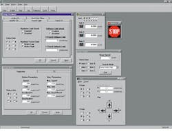
These controller systems have now moved to a PCI bus arrangement, the most recent data transfer standard. This allows programming under Windows 95 or NT operating systems, which provide the user with a more-interactive graphical user interface (see Fig. 2). In some applications, there will be no need for an additional data-acquisition board, due to the high processing power of digital signal processors (DSPs), thus saving space in the computer as well the initial cost.Bringing the components together
Newport's new ESP6000 motion controller, combined with the "smart" Uni drive6000 driver card and ESP-compatible positioning stages, provides an example of a system that can auto-configure. This new platform reduces overall complexity, takes less physical space (and in some configurations, less computer space), reduces service inventories, and can improve productivity. Because it processes information ten times faster than previous Newport and competitive systems, it does a better job of performing more-complex types of motion, including circular interpolation or helical motion, where the computer and controller must synchronize the motion of multiple axes. In certain modes of acceleration, these systems are much better at performing "S" curve profiling, a feature that smooths out the acceleration by working with the derivative of the acceleration also known as the "jerk." The system is able to accelerate faster and provide faster settling times due to more-timely feedback from the stage.
Two other features further enable submicron positioning (see Fig. 3). A maximum encoder data rate of 16 MHz provides the high bandwidth necessary for submicron motion, and the 18-bit DAC (digital-analog converter) command output improves stability for these applications. The system can also function in a multitasking environment.Finally, it is hard to overestimate the importance of well-thought-out user interfaces. In the case of the ESP6000, one part of the programming simplifies servo-tuning—normally a painstaking, iterative, and frustrating job—by the use of on-screen graphics, which are mouse-controlled for finer control. The visual images resemble the slides and gauges of a sound-control board, allowing a visual check for position as well as color-coding the results. Once the stage is tuned to an acceptable level the tuning parameters can be saved to the nonvolatile flash memory on-board the ESP6000 motion controller so that they do not need to be recreated each time. Also, for ease of use, even the error codes are descriptive, making troubleshooting and problem-solving simpler.


