Laser Drivers: Using a laser diode or quantum-cascade laser? Don’t forget the electronics

JAKE R. LINDQUIST
Drive electronics play a significant role in laser diode (LD) and quantum-cascade laser (QCL) system performance. Both laser types have specific electrical requirements based on their design. Laser diodes have a forward voltage requirement that is dependent on the bandgap of the materials used to make the diode itself. Quantum-cascade lasers have higher forward voltage requirements dependent on the number of multiple-quantum-well (MQW) heterostructure periods engineered into the design.1
In addition to supplying adequate voltage, drive electronics must properly control current output to the laser. There are other critical specifications that must be taken into consideration to ensure that the driver is well suited for the laser application, such as compliance voltage, current capacity/stability, noise, bandwidth, and laser protection.
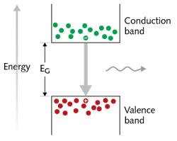
A laser diode’s emission wavelength is determined by the energy bandgap between the conduction and valence bands of the materials used to manufacture the laser diode (see Fig. 1). The wavelength of the emitted photon can be calculated, given the energy of the bandgap, using
EG = hc/λ
where EG is the energy of the bandgap, h is Planck’s constant, c is the speed of light, and λ is the wavelength of the output light.
For current to flow through the diode, it must be forward-biased. The voltage at which the diode is able to lase is referred to as the threshold voltage. Threshold voltage varies from approximately 2 V for red and infrared LDs up to 8 V for green/blue LDs. Similarly, there is a threshold current. Up to the threshold current, there may be no radiative emission at all, or there may be spontaneous emission. Above the threshold current, there will be coherent stimulated emission (lasing).
Different requirements for QCLs
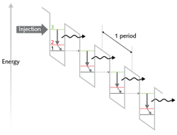
Quantum-cascade lasers operate on different physical principles from laser diodes and require higher voltages to establish the cascaded population inversion. Instead of electrons emitting a photon when transitioning from the conduction band to the valence band, electrons in QCLs emit photons when undergoing inter-subband transitions. QCLs are engineered such that the electrons remain in the conduction-band energy levels throughout the lasing process.
To accomplish this, a periodic MQW structure is manufactured. The allowable electron wavefunctions for these quantum-well structures are known, and are designed to take advantage of quantum-mechanical tunneling of the electron from one well to an adjacent well. Tunneling is also responsible for the quantum efficiency of greater than unity that is achievable with QCLs, but not with LDs. This is because of the fact that in LDs, once the electron has settled back in the valence band, it has emitted the only photon that it is energetically allowed to. In QCLs, once the electron transitions down from the upper lasing state, it can then nonradiatively decay to another lower state (which has been engineered to coincide with the adjacent well’s upper lasing state), tunnel to the adjacent well, and then transition down from this new upper lasing state. Hence, a single electron can emit up to N photons, where N is the number of periods in the QCL structure (see Fig. 2).Because of this complex structure, QCLs have significantly higher voltage requirements than LDs. The voltage that is supplied to the QCL plays two major roles. First, the voltage determines the electric field that the QCL will operate in. Without a properly established electric field, the tunneling probabilities and lifetimes will vary,2 deteriorating the laser’s efficiency. Second, the voltage that is dropped in the active region without contributing to radiative emission is critical for maintaining population inversion (minimizing population in the lower lasing level).3
The compliance voltage specification on laser drivers determines compatibility with these voltage requirements. The value given for compliance voltage describes the maximum amount of voltage that the driver can provide to the laser at full current. The compliance voltage should always exceed the laser’s specified forward voltage requirement.
The current supplied to the laser from the driver is known as injection current. Similar to LDs, QCLs have a threshold injection current. The stability of both power and frequency output by the QCL or LD depends on the stability and noise of the driver current. There are many applications that require the laser to have a narrow linewidth and stable output frequency. There are also spectroscopic applications that take advantage of this relationship, and that use the injection current and temperature control to tune the output wavelength.
When tuning the output wavelength of a QCL, the two methods presented above offer two distinct ranges and speeds. Varying the injection current typically yields faster tuning with a smaller accessible tuning range. Varying the temperature of the QCL typically results in a slower tuning, but with a wider range.4 Recent literature has shown that more-tailored temperature tuning (for example, heating only near the active region or distributed Bragg reflectors,5 if present) can result in broader tuning ranges.
Noise considerations
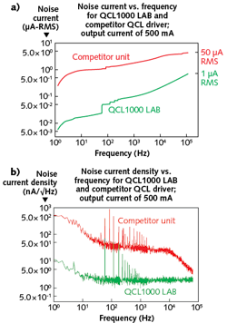
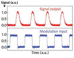
Semiconductors (including QCLs) are sensitive to 1/f noise. This is usually the dominant noise component up to the tens-of-kilohertz range. Noise from the driver directly affects performance. 1/f noise can impact the linewidth, so the noise output from the driver can be one of the limiting factors of the linewidth.6 Note that driver manufacturers specify the driver’s noise in different ways. Many drivers give a composite noise specification in units of μA root mean squared (RMS). A more-correct way to define a driver’s noise is to give the spectral noise density, which has units of nA/√Hz (see Fig. 3).The RMS noise specification is an integration of spectral noise density, and the associated bandwidth is the upper bound of this integration. When this specification is given, the associated bandwidth is critical to proper interpretation. For example, in Figure 3a, the Competitor Unit could be specified at a value of 0.5 μA RMS, but it would be at a bandwidth of <10 Hz, whereas the QCL1000LAB would be specified at 0.5 μA RMS at nearly 100 kHz. The value given for spectral noise density is the level that the noise density settles to after the 1/f noise contribution stops being the dominant factor.If the application requires the laser to be modulated, then the bandwidth specification of the driver needs to be considered (see Fig. 4). There are two specifications given for drivers with respect to bandwidth. The first is the frequency at which 90% depth of modulation (DOM) occurs. This value is relevant for square-wave modulation. The second specification is the -3 dB bandwidth of the driver, which is relevant for sine-wave modulation. The -3 dB bandwidth is the frequency at which the signal intensity has dropped by 3 dB (one-half of the input value). Both the DOM and the signal intensity decrease as frequency increases.
In addition to current, voltage, noise, and bandwidth performance specifications, optimal laser drivers will protect the laser as well. For example, safety features include: current limits to prevent overdriving the laser; voltage limits to protect the laser from reverse-voltage, over-voltage, and under-voltage scenarios; slow start current ramps; and interlocks to disable output if operating parameters deviate from the desired configuration.
Preventing laser failure
Since semiconductor lasers are unipolar, catastrophic failure of the laser could result from configuring the electronics incorrectly. Reverse-voltage protection, if built in, will allow alternate current paths (protection diodes, fuses, etc.) to prevent possible damage to the laser. Limits on the maximum current and maximum voltage are available to keep operational parameters within a safe zone. Slow start current ramps are built in to prevent unwanted thermal shock that can result from a step-wise enabling of current. The temperature change in the active region of the laser between disable and enable can be too drastic or too fast and damage the laser. By slow starting the current, the rate of change of temperature is decreased, allowing for a built-in thermoelectric cooler (or other temperature-control device) to more easily maintain a safe operating temperature. Some drivers incorporate a temperature-dependent interlock, which can be designed to disable output from the driver if the temperature gets too hot. Additional interlocks that only enable the driver if cases or doors are closed may be available as well.
Many parameters related to operating a QCL are specified, and it is important to ensure that the chosen driver is not the limiting factor of the laser system. A QCL driver providing stable, low-noise current and adequate voltage to the laser will allow for better system performance—meaning narrow linewidth and decreased spectral drift. If possible, choose a driver specifically designed to operate QCLs, which generally provides higher compliance voltage and lower noise current than a standard laser-diode driver, to meet the operating requirements of a QCL. Safety features are an additional aspect to consider when weighing driver options. A well-equipped driver can protect your QCL investment from improper configuration, thermal runaway, and supply transients that may end up overdriving the laser.
REFERENCES
1. C. Sirtori et al., Appl. Phys. Lett., 73, 24, 3486–3488 (1998).
2. R. Köhler et al., Nature, 417, 156–159 (2002).
3. Y. Yao, A. J. Hoffman, and C. F. Gmachl, Nat. Photonics, 6, 432–439 (2012).
4. K. Gürel et al., Photonics, 3, 3, 47 (2016).
5. S. Kalchmair et al., Opt. Express, 23, 12, 15734–15747 (2015).
6. T. L. Myers et al., Opt. Lett., 27, 3, 170–172 (2002).
Jake R. Lindquist is a technical writer at Wavelength Electronics, Bozeman, MT; e-mail: [email protected]; www.teamwavelength.com.


