How to design a laser scanning system
Ron Gibbs
Since their first uses in the 1960s, laser scanning systems have been designed and used for many applications, from supermarket barcode readers to very-large-screen (30-m) projection TV displays. The applications can be broadly classified as input (reader) or output (writer) systems.
In recent years, rapid advances in charge-coupled-device (CCD) detector arrays and inkjet technology have improved the performance of nonlaser input and output systems. Many applications remain, however, that can only be satisfied by the high speed and resolution that are possible with laser scanning systems. Laser technology has kept pace, especially in semiconductor and solid-state laser development, making new wavelengths and higher powers available to the system designer. Advances in optical and mechanical fabrication technology have improved the performance and reduced the cost of fast scanning mirror deflectors.
Scanning systems can take many different forms, ranging from simple to complex. They can include subsystems for reflected/transmitted/scattered beam measurement (input), modulation and intensity control (output), feedback control of beam power and position, and beam expansion and path folding. At the heart of every system, though, is the deflector/focusing subsystem, which largely determines the performance and cost of the overall system.
System specifications
To demonstrate the process for designing a scanning system, consider a hypothetical system specification for a high-performance output image recorder (see Table 1). This process uses a laser to expose a green-sensitive material to form a monochromatic image. Applications might include commercial printing, medical-image hardcopy, or photomask production.The basic system-configuration choices are flat or curved image surface, single- or multiple-facet deflector, and single- or multiple-laser beams. The form of the image surface has important implications for automatic handling of the imaging medium. Some surfaces (electronic circuit boards, for example) are rigid and there is no choice but to use a flatbed. Even for flexible film and plates, automated handling is much less complex for flatbed configurations than for internal or external cylindrical drums.
Angular scanning deflectors naturally produce a curved image surface, however, unless they are followed by a lens system that introduces a compensating positive field curvature. Generally, the advantages of simpler medium handling outweigh the additional lens complexity, and flatbed systems are preferred where possible.
Choice of laser
For the material response, the laser wavelength must be within the 500-550-nm range. The three possibilities are a 514.5-nm argon-ion laser, 532-nm frequency-doubled Nd:YAG laser, or 543-nm HeNe laser. An important consideration is the laser power requirement, which is given by
(omitting measurement unit conversion factors) where h is the scan duty cycle, and T is the optical system transmission.
The duty cycle must meet the requirement for maximum modulation frequency. The average data rate fdata is calculated from
which is 16.9 Mbyte/s for this system. The minimum duty cycle h is calculated from to be 56.3%.
If we assume a value of T = 50%, the laser-power requirement is 25 mW. In real photosensitive materials, the response will vary with wavelength and should be calculated for each candidate laser.
The final choice of laser can involve a complex assessment of a combination of power stability, mode structure, reliability, cost, size, and power consumption. For the purposes of this example, we will design for a 532-nm diode-pumped Nd:YAG laser.
Specification of lens
To determine whether a flatbed configuration is feasible, we must calculate N, the number of resolved spots required per scan line. In the example system,
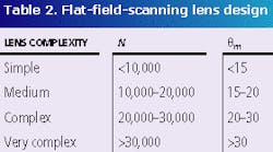
N = 14,663 for a scan line along the 297-mm format width. This is well within the capabilities of typical flat-field-scanning lens designs of medium complexity (see Table 2).It may well be possible to select an appropriate lens from a supplier's standard range. This is usually preferable to designing a custom lens, saving significant design and tooling costs and greatly reducing the lead time to obtain the lens. Scan lenses can be designed for f-theta distortion correction and/or for telecentricity, in addition to field curvature correction.
The f-theta distortion correction is required for a constant scan velocity at a constant deflector angular velocity. This is highly desirable for an exposure system, as the laser power and the modulation data rate are then constant along a scan line. Conventional lens distortion correction results in a scan position of f.tan theta for a scan angle of q. By designing into the lens the correct amount of barrel distortion, the scan position can be made to be f.theta.
A telecentric scan lens is one in which the chief ray of the focused beam is parallel to the optical axis at all scan angles. This condition ensures that the focused spot size does not vary with scan position due to its projection angle on the image plane and that the scan position is not shifted by image defocus. In practice, this condition is not essential for most systems and should not be specified unless absolutely necessary as it adds significantly to the size and complexity of the lens.
The fundamental lens parameters are the focal length, f, the maximum field half-angle, thetam, and the aperture, DL. For a given focal length f/theta lens, the minimum field angle is calculated from
In our example system, a 500-mm focal length requires a field angle of 17.0°. The lens must be corrected for at least this field.
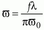
Most commonly, the input beam is collimated, although alternative configurations are possible in which it is weakly converging. For a collimated input, the beam radius at the lens entrance pupil is the same as the size at the deflector, and is simply calculated from
for a TEM00 Gaussian beam.
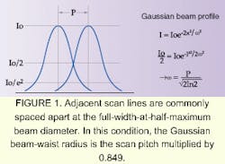
The beam waist at the image plane is related to the scan pitch p (=1/R) by w0= 0.849p. At this size, adjacent scan lines overlap at 50% peak intensity, which gives good image sharpness together with low raster line visibility in flat image areas (see Fig. 1). The ideal spot shape is elliptical, with a smaller size in the scanning direction, but in practice a round beam of this size gives good imaging results in most cases. If DL>4w (14.2 mm) a wavefront correction of l/4 will give good imaging with no beam truncation.
Design of polygon mirror
The most commonly used form of polygon deflector is prismatic, where the mirror planes are perpendicular to the rotation axis and the incident and reflected beams are also perpendicular to the rotation axis (see Fig. 2). In this configuration, the reflected beam is deflected by twice the deflector rotation angle.
The number of facets and the size of the polygon are the key parameters that need to be defined (see Fig. 3). These should be minimized to reduce the cost of the polygon. They are derived from the duty-cycle requirements and the collimated beam size.
The number of facets, n, is determined by the requirement that
For our target duty cycle of 0.563, this leads to n> 11.9, so the minimum number of facets is 12. The number of facets and the scanning line rate determine the rotation speed of the polygon. In our example, the line rate is 1152 lines/s, so the polygon rotation rate is 5760 rpm. This is not a difficult rotation speed to achieve using air bearings.
The duty cycle is limited by the unusable scan dead time resulting from the passage of the corners between mirror facets across the input beam. This sets a limit on the minimum size of polygon. The effective beam size is increased along the length of the mirror facets by the angle of incidence, so the smaller this angle, the greater the duty cycle for a given size of polygon. For a specific scan lens, the minimum usable angle can be calculated from the layout geometry, using the physical dimensions of the lens housing and the input beam size.
The facet length is calculated from
And the minimum circumscribed (outer) diameter of the polygon is calculated from
where DP is the beam aperture, phi is the deflection angle at the center of the scan line, and d is a polishing allowance (~1 mm).
For simplicity, we will design for phi = 90°, so that the input and lens axes are at right angles. This leads to a simple mechanical layout and does not impose any restrictions on, or make any assumptions about, the lens housing. We will use a value of DP of 2w multiplied by a factor of 1.7 (= 12.1 mm), which avoids beam-truncation effects. This results in a value of DF = 160 mm (LF= 41.3 mm) for our 12-faceted polygon. The polygon thickness t must be sufficiently large for the collimated input beam, plus an allowance (~1.5 mm) for alignment and polishing/coating edge effects. An additional condition is that t must be >DF /12, to ensure that the polygon substrate is sufficiently rigid for accurate fabrication, which leads to a minimum thickness of 13.6 mm.
Not a perfect solution
The design process for a laser scanning system has been presented here as a systematic calculation of design parameters from system requirements, which leads to an efficient design solution. In practice, this process will not work perfectly in all cases, but the basic structure provides a good starting point for analysis. The process could fail by requiring laser power, polygon rotation speed, or polygon size that is unfeasible. In this case, design alternatives must be sought.
Simple modifications to the process include reducing the laser power requirement by further increasing the scan duty cycle and reducing the polygon size by decreasing the central deflection angle. More-complex solutions could include multiple laser beams, integral optical-deflector error correction using anamorphic optics, or alternative forms of focusing optics and/or scanning deflector.
It is useful to incorporate these calculations into a computer spreadsheet, so that the effect of the various specifications on the laser, lens, and polygon design parameters can be easily seen. This allows design breakpoints and trade-offs to be quickly and easily identified and can be adapted for analysis of more-complex systems, such as multiple-beam systems.
RON GIBBS is an independent consultant specializing in the design of laser and optical scanning systems at Gibbs Associates, 82 Tring Rd., Dunstable LU6 2PT, England; e-mail: [email protected].


