Piezoelectric technology eases navigation in the nanoworld
Many high-tech industries have come to rely on the continuing progress in piezoelectric nanopositioning and micropositioning technologies.
Although seldom recognized, there is a fundamental difference between nanopositioning and micropositioning systems—the way in which they deal with friction. When friction is present, it is not possible to achieve repeatable motion at the nanometer level and below. True nanopositioning systems must be equipped with frictionless drives and guides. Mechanisms that rely on mechanical friction to produce motion (like lead screws) or confine motion (such as ball bearings or roller bearings) are called micropositioners.
The virtually unlimited resolution and extremely fast response of piezo devices have made them a cornerstone of ultraprecision applications from nanometrology to nanomanipulation. Today a large variety of piezo-based positioning systems is available, from simple open-loop actuators, to complex flexure-guided nanopositioning systems and piezo linear motors. All piezoelectric drives are ceramic-based, and can operate in a vacuum; they do not produce magnetic fields nor are they influenced by them.
Piezo actuators
Piezo actuators are solid-state devices with unlimited resolution. Their travel ranges are typically a few hundred microns or less—they do, however, achieve forces in the kilo-Newton (kN) range, accelerations up to 10,000 g, and have much higher bandwidths than other drive types, enabling them to respond to commands more rapidly.
Modern multilayer piezo actuators are sophisticated sandwiches of ferro-electric ceramic layers interleaved with electrodes, not unlike ceramic capacitors. They are maintenance-free, and provide response on a microsecond time scale.
A major breakthrough in the manufacture of piezoelectric devices is the development of ceramic-encapsulated actuators (see Fig. 1). Benefits include superior protection from moisture, wider operating-temperature ranges, vacuum-compatibility with zero outgassing, response on a microsecond time scale, and improved attachment stability of feedback elements such as piezoresistive sensors (used in entry-level nanomechanisms).
Piezo linear motors
Piezo linear motors can be divided into two groups: “continuous” (resonant, ultrasonic) motors and “step” motors. Both can, in principle, attain unlimited travel. Continuous motors are characterized by higher speeds, step motors by higher resolution. A great advantage of piezo motors is their intrinsic steady-state auto-locking capability. It can eliminate servo dither and the accompanying heat generation, a downside of electromagnetic motors. Step and continuous piezo motors are nonmagnetic and vacuum-compatible, a requirement for many applications in the semiconductor industry.
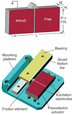
The key element in the new motors is a rectangular monolithic piezoelectric plate (the stator), segmented on one side by two electrodes (see Fig. 2). Depending on the desired direction of motion, the left or right electrode is excited with a sine-wave signal at a specific frequency of tens to hundreds of kilohertz, while the second electrode remains passive. The resulting, asymmetric, two-dimensional standing wave is transferred to a pusher made of alumina, which is preloaded against a friction bar mounted on the moving portion of the translation stage. The motion provides micro-impulses at very high frequency, driving the slider.State-of the-art ultrasonic motors can produce accelerations to 20 g and velocities to 800 mm/s. Force generation, once a drawback of resonant motors, has also recently made a big step forward. Single-element motors with pushing forces of up to 50 N are now available.
Ultrasonic motors cannot provide the unlimited resolution of piezo actuators and flexure-guided piezo positioning stages. It has to be understood that these motors transfer motion through friction, which is why their repeatability is limited to about 50 nm.
Piezo step motors offer higher resolutions. They usually consist of two or more individual piezo elements and generate motion through succession of coordinated clamp/unclamp and expand/contract cycles. Each extension cycle provides only a few microns of movement, but running at hundreds or thousands of Hertz, achieves velocities of several mm/second.
Traditionally, piezo step motors consisted of a number of thin-walled lead zirconate titanate (PZT) ceramic tubes traveling along a rod, like a monkey climbing up a rope. While providing subnanometer resolution, they were quite delicate with forces limited to a few Newtons and relatively short lifetime affected by micron-scale wear.
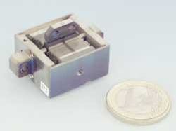
Newer designs (piezo walk motors) are based on more-rugged actuators and incorporate a preloading mechanism to provide pushing and holding forces greater by two orders of magnitude (up to 600 N) with basically unlimited lifetime (see Fig. 3). Such motors combine two operating modes: in long-range step mode, motion consists of user-defined (or auto-ranging) steps with widths from less than 20 nm to 2 µm in size; in fine-adjustment, analog mode the clamps are on and expansion/contraction motion with subnanometer resolution over a travel range of 2 µm is used alone.Flexure-guided nanopositioning stages
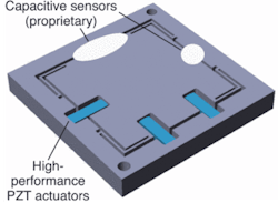
Flexure-guided piezo-driven nanopositioning stages are the highest precision motion systems currently available (see Fig. 4). The high resolution and extremely fast response of these devices have made them crucial in ultraprecision applications such as scanning microscopy, interferometry, surface profiling, photolithography positioning, and wafer/mask inspection and repair systems.A piezo nanopositioning stage consists of three key elements: a precision guidance mechanism, a piezo actuator to provide the motion, and a sensor to measure the exact position of the stage. A highly specialized digital or analog servo controller is also crucial to achieving accuracy in the nanometer realm and below.
Guidance
For a nanopositioning stage to perform well, it is vital that the motion be guided in (confined to) the desired direction, without causing friction. For this reason, the highest precision nanopositioning systems are generally guided by electrical-discharge-machined (EDM) flexures. A flexure is a frictionless, stiction “linkage” that relies upon the elastic deformation (flexing) of a solid material. Flexures require no maintenance, no lubricants, exhibit no wear and are ultra-high-vacuum compatible. They also can accommodate multi-axis arrangements and can be designed to leverage the motion input of a piezo actuator by more than one order of magnitude.
Not all flexures are created equal, however. Simple parallelogram designs cause runout errors on the order of 1%. Guiding precision in the nanometer range can be achieved by more-complex multilink designs. Careful attention to decoupling the actuator from the stage insures that only motion in one degree of freedom is transferred.
Position feedback
Strain-gauge measurements are based on the resistance change in a thin film of fine metallic wire, foil, or semiconductor (piezo-resistive) material; strain is transferred through a thin adhesive layer to the sensor bonded to the surface of an actuator or other component in the drive system. Strain-gauge sensors can provide high resolution and bandwidth but they cannot detect motion inaccuracies such as elastic deformation or drift between the sensor mounting point and the moving platform carrying the payload.
Capacitive sensors have emerged as the first choice in direct metrology nanopositioning systems. They are compact noncontacting devices measuring the capacitance between electrodes integrated in the fixed frame and the moving part of the stage. The capacitance is proportional to separation of the electrodes and hence a direct indication of position.
Direct metrology devices, such as capacitive sensors, monitor the moving part of a system directly and see any flex or other errors in the drive train—from the actuator through the lever and flexures to the platform. This results in higher phase fidelity, motion linearity, long-term stability and-because external disturbances are seen by the sensor immediately—a stiffer, faster-responding servo loop.
Advances in multi-axis designs
In many nanopositioning applications, such as cell tracking, image stabilization, or photonic alignment, high-speed motion in more than one dimension is required. Conventional multi-axis systems are made by stacking a number of single-axis subassemblies (serial kinematics design). In these designs, each axis moves the mass of all the stages that are mounted on it, as well as their cables.
Novel multi-axis systems with only one moving platform are known as monolithic parallel-kinematics stages. The advantage of these designs is that they significantly reduce inertia and size, and they offer improved dynamics. They also allow easy integration of multiple capacitive sensors in a parallel metrology configuration with both the x and y measurements made relative to “ground” (the fixed frame).
Both sensors thus detect runout and crosstalk of the orthogonal axes and the servo loop compensates in real time. This technique is called active trajectory control and can provide guiding accuracy in the subnanometer realm. Benefits include reduced blurring of edges in high-speed imaging applications (scanning microscopy, for instance), resulting in higher image resolution, faster response, and multi-axis accuracy in any type of precision probe alignment, positioning and scanning.
Today, nanopositioning systems with up to six degrees of freedom are available, with virtually no crosstalk between individual motion directions.
Dynamics
In today’s throughput-driven production and testing processes, requirements often read “nanometer precision in milliseconds.” Because piezo drives can provide extremely high acceleration, some flexure-guided stages can respond to an input signal in less than 0.1 ms. To help payloads keep up, modern control algorithms such as Input Shaping, offered by Convolve (New York, NY), prevent self-generated resonances and eliminate the settling phase altogether.
At high scanning speeds, as desirable in scanning microscopy applications, conventional PID servo-controller designs produce a following error. This error—the difference between the desired position and actual position, also known as tracking error—can reach double-digit percentage values and more. Recent advances in controller design have lead to dynamic digital linearization methods that reduce tracking errors from the micron realm to almost indiscernible levels.
Piezoelectric positioning systems are today’s most valuable tools for exploring and manipulating the nanoworld. Because of the numerous choices, selecting the right system for a specific application can be complex and can often benefit from working with experts who are familiar with a variety of technologies.
About the Author
Stefan Vorndran
Stefan Vorndran is VP of marketing at PI (Physik Instrumente; Auburn, MA).


