Rotational flexures deliver high precision
BILL O'BRIEN
Many applications now demand high-speed rotational motion, ultrasensitive rotational motion, or both. In a typical application a laser beam is steered across a sample using a rotational stage, often with two-axes. An experiment might rely on fast scanning to rapidly survey large areas; once an interesting area is found the scan range is minimized to get more-detailed information. The area to be zoomed in on can be as small as a single molecule.
Over the past five years, technical advances have allowed the nanopositioning industry to reach unprecedented levels of precision and speed. It is now possible to manufacture linear nanopositioning stages capable of subnanometer resolution and operation at speeds near a kilohertz. The important technological advances that have made these devices possible are found in the manufacturing of multilayer piezoactuators, the design of flexure hinges, and in the use of piezoresistive sensors. These same technological advances can also be applied to rotational stages. Such a stage would have nanoradian-level precision and be able to operate at speeds near a kilohertz.
Stage components
A rotational stage contains three primary components: the actuator, the guidance mechanism, and the position sensor. The most suitable actuator for nanoradian precision is the multilayer piezoactuator.1 Multilayer piezoactuators are thin wafers of lead zirconate titanate (PZT). Under an applied electric field, this material changes its length in a somewhat linear fashion with the applied field. The maximum length change or strain achieved is about 0.1%. These actuators are built from many thin layers of PZT that are connected electrically in parallel but physically in series. They give displacements up to about 100 µm with a typical applied voltage of 150 V. The step resolution of these actuators is better than a fraction of an angstrom, making them uniquely suited for rotational stages requiring nanoradian resolution.
Rotational flexure hinges are the ideal guidance mechanism for rotational stages requiring nanoradian resolution. In flexure hinges, no two parts that move relative to each other are in contact. This eliminates stiction, component wear, and nonreproducible contact points that are common in other types of guidance mechanism such as bearing stages. The displacement of the flexure hinge results from the repositioning of atoms in the hinge (strain) and is 100% reversible as long as simple design guidelines are followed, including ensuring that the maximum strain in the hinge remains below the fatigue limit of the material used to construct the hinge.
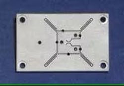
A rotational stage based on a flexure guidance mechanism has a resolution of 2 nrad and a 2-mrad range of motion, and is driven by a multilayer piezoactuator (see Fig. 1). The entire stage is constructed from one piece of aluminum and consists of an outer frame and the rotational platform. The rotational platform is connected to the outer frame by the flexure hinges, which are formed by electric-discharge machining. In this type of machining, a high voltage is applied to a thin wire that is used to cut through the material in a manner analogous to cutting butter with a hot knife. The cuts formed by electric-discharge machining can have arbitrarily high aspect ratios, a requirement for flexure hinges.
There are two types of rotational flexure hinges in this stage. The first, a right-circular hinge, is located at the center of the rotational platform. The right-circular hinge is formed by two back-to-back semicircles separated by a small distance. The axis of rotation for this stage is normal to the stage and is located halfway between the two semicircles along the line of their minimum separation. This axis of rotation is also permanently fixed in location, which is in contrast to rotational stages incorporating other guidance techniques such as those that rely on three piezoactuators pushing against a rotational platform. In such a rotational stage, the axis of rotation is not well defined or fixed in location. The stage will wobble if the axis of rotation is not permanently fixed in location. Such a wobble can induce parasitic deflections that will not be detected by any internal sensor, leading to positioning errors. A rotational stage incorporating a right-circular hinge eliminates these errors.
The second type of rotational flexure hinge contained in the example stage is the group of four hinges located at the corners of the rotational platform. These tangential flexure hinges are designed to increase the stiffness of the stage and eliminate any coupled motions. Increasing the stiffness of the stage allows the stage to operate at higher speeds. By placing the tangential flexure hinges at the outer edges of the rotational platform, the rotational stiffness and therefore the speed of the stage is maximized. Unwanted coupled motions, or parasitic motions, are minimized by stiffening the stage in the directions orthogonal to the rotational motion. The tangential flexures add a stiffness of 3 × 10⁹ N/m orthogonal to the rotational motion. For this particular stage, the parasitic rotations (rotations about axis orthogonal to primary axis of rotation) are less than 1 µrad.
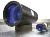
The example rotational stage is a single-axis stage. The same design principles can be used to create a stage with two or three rotational axes (see Fig. 2). In an example rotational stage with two axes of motion, both axes are guided by right-circular flexure hinges and tangential flexure hinges. Such a stage has a 5 × 5‑mrad range of motion with a resolution of 4 nrad in each axis. The two axes of rotation are orthogonal to within 0.1 mrad.
Resonant frequency
The speed at which a rotational stage can operate is limited by the resonant frequency of the stage, which is in turn determined by the details of the flexure hinges. To determine the resonant frequency of a rotational stage, the appropriate equation of motion must be solved:
Id2/dt2θ = -Kθθ
where I is the moment of inertia of the rotating structure, Kθ is the rotational stiffness, and θ is the angle of rotation. The resonant frequency, νr, can be obtained by solving the equation:
νr = 1/2π (Kθ/I)1/2
The rotational stiffness of the stage is the sum of the stiffness of each rotational flexure hinge. The rotational stiffness of a right circular hinge has been calculated by Smith using finite-element analysis and tabulated using empirical formulas.2 The stiffness of the tangential hinges can be calculated and is:
Kθ(tan) = 2Etr2(w/l)3
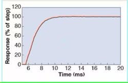
where E is Young’s modulus, t the hinge thickness, w the hinge width, l the hinge length, and r the distance of the hinge to the center of rotation. The moments of inertia of the rotational platform and any optics mounted to the platform (such as a mirror or prism) are summed to obtain the total moment of inertia. The resonant frequency of the example two-axis rotational stage is 3.5 kHz with the mirror attached. This allows the mirror to operate at high speeds. The step response of the stage is about 3 ms (see Fig. 3).
Piezoresistive sensors
To achieve nanoradian-level precision in a rotational stage, an ultrasensitive position sensor must be integrated into the stage. The best choice is a piezoresistive sensor. These sense motion through a change in the details of their bandgap, which is recorded as a change in resistance. Because they weigh only milligrams and have dimensions of millimeters, they can easily be integrated into any rotational stage.
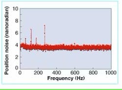
The main noise in a piezoresistive sensor is Johnson noise, which is calculated to be approximately 1 nrad for a typical rotational stage. This low noise value is because of the sensor’s low resistance and high sensitivity. The background noise level of the example two-axis rotational stage is about 4 nrad, suggesting that the noise comes primarily from the measurement electronics (see Fig. 4). In view of the fact that this stage has 5 mrad of motion, the noise-to-signal ratio is better than one part in 106.
In addition to being ultrasensitive, piezoresistive sensors are also highly linear-to better than 99.95%—and give a direct measurement of the stage’s rotation. Unlike other ultrasensitive motion sensors such as capacitance sensors, piezoresistive sensors can distinguish between stage rotation and translation. The lack of this ability is a serious problem for capacitance sensors in linear translation stages and rotational stages. Another advantage that piezoresistive sensors have over capacitance sensors is that they use a DC (unmodulated) measurement, which is inherently faster and quieter than the AC (modulated) measurement required for a capacitance sensor.
REFERENCES
1. B. Andersen et al., Proc. ACTUATOR 2004, 9th Int’l. Conf. on New Actuators and 3rd Int’l. Exhibit. on Smart Actuator and Drive Systems,, Bremen, Germany, 64 (June 2004).
2. S. T. Smith and D. G. Chetwynd, Foundations of Ultraprecision Mechanism Design 2, Gordon and Breach Science Publishers, Amsterdam, the Netherlands (1998).
Bill O’Brien is a member of the research and development group at Mad City Labs Inc., 2524 Todd Dr., Madison, WI 53713; e-mail: [email protected].


