Optics Manufacturing: CAM software package makes acylinder optics manufacturing easier and more efficient
Aspheric cylinders, or acylinders, are increasingly common in today's optical systems because of their ability to improve optical performance over standard cylindrical surfaces. Acylinders can be defined as cylindrical optics with an aspheric prescription on the convex or concave surface. Just as aspheres aid in a system's performance by reducing optical aberration, acylinders provide the same benefit when expanding or focusing light into a line. This type of optic is utilized in a variety of optical assemblies, including laser scanning and other laser-diode applications, spectroscopy, and optical processing.
Although acylinders optimize the performance of an optical system, they also present additional manufacturing challenges because of their geometric complexity. Acylinders are more difficult to manufacture than their cylindrical counterparts, and typically do not lend themselves to traditional manufacturing or metrology methods. Without the latest technology, cost-effective production can be difficult or impossible to achieve.
Efficient manufacturing of acylinders requires computer numerically controlled (CNC) machines with five axes of motion (x, y, z, B, and C) that are capable of optical grinding and subaperture polishing. Technological advancements have made these platforms more capable than ever at producing acylinders, provided that they are equipped with the appropriate computer-aided manufacturing (CAM) software.
For CNC optical grinding and subaperture polishing machines to perform necessary processing operations, CAM software is needed to "drive" the machines by generating toolpaths. Toolpaths tell the grinding or polishing tool to move in a specific direction to create the desired surface.
CAM software
Until recently, traditional CAM software designed for the metalworking industry was the only commercially available solution for manufacturing acylinders and other nonrotationally symmetric optics. Many limitations exist in traditional CAM software, including how surface points and toolpath motions are distributed across a complex shape. In addition, traditional CAM software is unable to generate compensated toolpaths based on metrology feedback. Metrology-driven figure correction is a crucial step in the manufacturing process to achieve submicron surface form error specifications. Because this level of precision is not common in metalworking, CAM software designed for machining metals is not an ideal solution.
As a result, OptiPro Systems developed PROSurf, a CAM software package that eliminates the shortcomings in traditional CAM software. PROSurf is tailored specifically to manufacturing acylinders and freeform optics. With this software, surface point distributions are optimized for acylinders to ensure toolpaths guiding the grinding and polishing tools result in predictable surfaces. In addition, metrology-driven corrective toolpaths can be created to achieve high-precision surface quality. When used in conjunction with OptiPro's optical manufacturing and metrology equipment, the features of PROSurf make setting up and running acylinders adaptable for manufacturing.
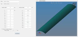
The process to create an acylinder begins by defining the surface in the software. This step is done during the job setup by entering the aspheric coefficients into the surface definition screen (see Fig. 1). Once the acylinder is defined, the software generates a specialized toolpath called Rapid Material Removal to rough-grind the acylinder on OptiPro's eSX optical grinding machine. This toolpath is designed to efficiently remove material from the rectangular blank to create the rough surface as fast as possible.
After the initial rough-grinding run, the acylinder is removed from the optical grinder and placed on a contact profilometer, such as OptiPro's OptiTrace 5000, for surface measurement. A 2D profile trace is performed across the surface of the acylinder. The metrology data from the trace captures form inaccuracies on the part induced by tool shape error. The data is subsequently imported into PROSurf to generate a compensated toolpath for figure correction with the rough-grinding tool. The corrections applied to the part are done so by changing the position of the tool. The tool is lowered in the z-axis direction where there is too much material on the surface. Conversely, the tool is raised where too much material was removed during the first rough grinding run.
Once rough-grinding corrections are applied, a 2D surface measurement is taken to set up the fine-grinding process. By referencing metrology data of the surface after the rough grinding correction, the operator determines the location of the fine grinding tool relative to the part. Then, the same procedure that was executed for rough grinding is repeating for fine grinding.
After fine grinding, OptiPro's UltraForm Finishing (UFF) technology is used to further improve the surface of the acylinder. UFF is a deterministic subaperture polishing process ideal for acylinders and other nonspherical shapes. The technology involves a moving belt of polishing material wrapped around a precision compressive wheel. The wheel is made of a compliant material and can be manufactured to various diameters and durometers. The belt may be bound with abrasive materials, such as cerium oxide and diamond, or made of a polyurethane material traditionally used in optical polishing. A combination of wheel diameter and hardness with the assortment of belts allows the operator to control how much material is removed.
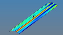
First, the surface is "grayed out" with UFF, meaning that excess material that makes the surface appear gray and foggy is removed to yield a clearer and more polished surface. The acylinder is then placed on the OptiTrace 5000 and multiple traces are performed across the surface to create a 3D error map (see Fig. 2). This 3D error map is imported into PROSurf to create a corrective toolpath for UFF polishing.While figure corrections with a grinding tool are made by adjusting the relative position of the tool, corrections made with UFF are dwell-based. This means that the UFF polishing tool is compressed into the part with the same force during the entire correction run, but the amount of time the tool stays in contact with a certain area on the part is dependent on the amount of surface form error. The more error on the surface, the longer the wheel will pause. This controlled motion reduces form error and eliminates grinding damage.
High-precision production
Process data from an acylinder manufactured on the eSX 300 optical grinding machine and UFF 300 polishing machine show the ability to achieve efficient production with high precision. The screenshot in Fig. 3a displays measurements taken on the OptiTrace 5000 before and after the fine grinding correction. The gray line represents the trace taken of the initial ground surface with a peak-to-valley (PV) of 38.881 μm and a root-mean-squared (RMS) of 10.298 μm. The red line denotes the measurement taken after a fine-grinding correction. The data shows a significant improvement in surface quality as the PV and RMS were measured at 3.525 and 0.584 μm, respectively.The polishing correction demonstrated the ability to reach high-precision surface quality with the UFF 300. The screenshot in Fig. 3b shows the acylinder surface after the fine-grinding correction (gray line) and after the polishing correction (red line). The polishing correction resulted in an improvement in PV from 3.525 to 0.453 μm, while RMS improved from 0.584 to 0.088 μm.
Manufacturing acylinders was once a time-consuming and iterative process that required highly skilled opticians. New optical manufacturing technology has changed the industry, allowing companies to take on acylinder jobs with confidence. This technology can help precision optics companies to produce acylinders more efficiently than ever before.
Pat Bechtold | Marketing Technologist, OptiPro Systems
Pat Bechtold is Marketing Technologist at OptiPro Systems (Ontario, NY).
Frank Wolfs | Senior Algorithm Engineer, OptiPro Systems
Frank Wolfs is Senior Algorithm Engineer at OptiPro Systems (Ontario, NY).


