Photonics Modeling Software: TCAD software facilitates comprehensive VCSEL modeling

Z. Q. (LEO) LI, AHMED NASHED, and SIMON LI
Widely used for optical storage, high-speed data transmission in optical networks, and laser printing applications, vertical-cavity surface-emitting lasers (VCSELs) feature low threshold current, a circularly symmetrical beam, and rapid modulation speed. Furthermore, VCSELs can be batch-fabricated in two-dimensional (2D) arrays for high-power applications and are amenable to on-wafer testing because of their vertical output-saving substantial measurement time and reducing manufacturing costs.
With increasing optical power and wavelength range (340–2600 nm), VCSELs are encroaching upon the application space of traditional edge-emitting lasers. And even though VCSEL performance has progressed significantly in recent years, researchers are still striving to improve the basic structure to achieve even higher output power and modulation speed.
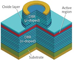
Standard VCSELs have a more complicated structure than edge-emitting lasers (see Fig. 1). With distributed-Bragg-reflectors (DBRs) at top and bottom, an active region with multiple quantum wells at the middle, and oxide layers to confine the carrier transport and optical power, more complicated variations can be experimentally fabricated and tested using time-consuming and costly processes. But a new alternative that reduces cost and turnaround time is technology computer-aided design (TCAD), such as that developed by Crosslight Software.
A modeling solution
Using TCAD, a VCSEL design is analyzed and characterized even prior to the fabrication of a new device. The measured results from this initial design are then used to correct the parameters of the model, and the design procedure is repeated. In this way, the accuracy of predicting device behavior is continuously improved and the number of prototype fabrication cycles is lowered.
For fabless design of VCSELs, reliable and robust software with multiphysics models and accurate material parameters is prerequisite. At Crosslight, our VCSEL simulation software combines comprehensive electrical, optical, and thermal models. For the past 10 years, we have worked with major VCSEL manufacturing companies to improve the theoretical models and calibrate the material parameters. Our PICS3D software package has been used extensively for characterizing VCSEL structures for their current-voltage (I-V), power-current (L-I), temperature distribution, multimode near- or far-field pattern, and small and large signal-frequency modulation response.
Beyond these basic parameters, more detailed information, including carrier distribution, electric field, band-diagram structure, and quantum-well or quantum-dot confinement states, can be determined-extremely important information for the design of new VCSEL structures.
Because of strong interactions between electrical, optical, and thermal effects in the device, the software must solve all relevant equations in a self-consistent manner. For the electrical component, for example, the software solves so-called semiconductor drift-diffusion equations to determine the carrier concentrations and electric potential distribution using a 2D/3D finite-element method (FEM). Photon-rate equations based on the round-trip gain are also solved at the same time to determine the photon density of the laser cavity.
For laser structures with quantum wells as the source of light, the confined quantum states may be found by solving the Schrödinger equation together with Poisson's equation. Optical intensity is obtained from the Maxwell equations with proper boundary conditions.
An easier way to solve Maxwell equations for VCSELs is to use the simple scalar approximation, which is based on the assumption that the optical field in a laser cavity is in the form of plane wave. This method is fast for common VCSEL structures with a cavity size much larger than the laser wavelength, and has been widely used for optimizing VCSEL structures. However, researchers are now trying to use aperture size to reduce the threshold current and maintain single-mode operation.
For suppressing higher-order lateral modes, researchers have also invented surface-relief structures. In these cases, for which the scalar optical approach is no longer valid, we offer more-complicated (100X more computational time) but effective vectorial optical approaches that require a coupled solution of all components of both the electric and magnetic fields.
Because of its smaller cavity size and current crowding, self-heating effects are important in VCSELs. Highly doped DBR regions with many material interfaces have smaller thermal conductivities than the bulk materials. Therefore, the temperature distribution is highly non-uniform, which is critical for the performance of the device.
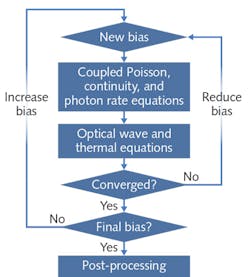
There are several heat sources inside the VCSEL cavity that contribute to the self-heating effects as the injection current ramps up. Joule heat generated from the carrier transport contributes the most to the heat flux. Other sources such as the recombination heat, Thompson heat, and radiative heat are also included in the heat conduction equation. To manage the interplay between these thermal and aforementioned electrical and optical VCSEL parameters, the modeling software follows a consistent series of steps (see Fig. 2).Flow-charting the software
Starting from an equilibrium condition where there is no bias on the contacts of the device, the drift-diffusion equations are first solved for the carrier densities and electric potential, coupled with the photon-rate equation.
Next, we solve the Maxwell equation and thermal equation to get the optical wave intensity and temperature distribution. The temperature-dependent material parameters, the modal gain, and the refractive index are updated for the next iteration. The procedure is repeated until the desired bias is reached, and then the results are post-processed to get the characteristics of the device.
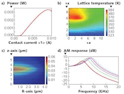
Simulation results interesting for VCSEL designers include the L-I curve showing the thermal roll-over of the laser power at high current injection, the temperature distribution of the device, and the optical-wave intensity for the fundamental lateral mode obtained from a vectorial optical mode solver (see Fig. 3). Multimode and far-field profiles are also available, as well as the frequency response of the device calculated from small-signal alternating-current (AC) analysis.In cooperation with major laser manufacturers, PICS3D software from Crosslight continues to be improved to facilitate next-generation reliable VCSEL structures.
Z. Q. (Leo) Li is vice president of engineering, Ahmed Nashed is research engineer, and Simon Li is founder and CEO, all at Crosslight Software, Vancouver, BC, Canada; e-mail: [email protected]; www.crosslight.com.

