SOFTWARE & COMPUTING: LIGHTING DESIGN: Colored light sources place new demands on lighting design software
Professional lighting designers, including architects and electrical and municipal engineers, rely on lighting design and analysis software to calculate lighting levels for buildings and roadways. While their designs must satisfy national and international lighting standards in the interest of public safety, they must also address aesthetic and often artistic expectations; good lighting is something we can all appreciate.
Lighting design and analysis software must therefore fulfill two roles. First, it must be able to accurately predict the distribution of light in an architectural environment; second, it should (but not necessarily must) be able to generate physically plausible images of the environment. Tables of numbers and plots are useful, but "a picture is worth a thousand words" when designing with light.
Today's software fulfills these requirements nicely, but the introduction of solid-state lighting based on high-brightness light-emitting diodes (LEDs), together with a renewed emphasis on natural daylight as a light source within the architectural community, is bringing new capabilities to both commercial and open-source products.
Theory
Professional lighting design is first and foremost an engineering discipline. For electric lighting, it begins with measured luminous intensity distributions ("photometric data") of the lighting fixtures (luminaires). This information is typically provided by the luminaire manufacturers and is the equivalent of sealed engineering drawings for their products.
For natural daylight, there are several "sky models" that accurately predict the distribution and intensity of direct sunlight and diffuse daylight, based on time and date, geographic location, and weather conditions. There are also available historical weather data for most locations to facilitate predictions of annual daylight conditions on a day-by-day and hour-by-hour basis.
The next step is to model the architectural environment. In years past, this consisted of specifying empty rectangular rooms with assumed reflectances for the walls (50%), ceiling (80%), and floor (20%). For roadway environments it was even simpler: hand calculations of direct illumination using the inverse square law. Today, it is common for the lighting designer to import three-dimensional computer-aided design (3D CAD) drawings, often with stunning complexity, from an architectural design program. The lighting designer then assigns material colors or textures to each surface, which automatically determines its reflectance, and photometric data for the luminaires.
Now art meets science as the software iteratively calculates the distribution of light within the 3D model. It begins with calculation of the direct illumination of each surface due to the electric lighting and (if present) daylight. Depending on the surface material properties, some of this light will be absorbed, while the remainder will be reflected or transmitted ("bounced") to other surfaces.
| Lighting design software products available for professional lighting designers | ||
| Product | Manufacturer | URL |
| AGi32 | Lighting Analysts | www.agi32.com |
| DIALux | DIAL GmbH | www.dial.de |
| Optis | Optis | www.optis-world.com |
| OptiWin | Glamox International | www.glamox-international.com |
| Radiance | Lawrence Berkeley Laboratory | radsite.lbl.gov |
| Relux | Relux Informatik AG | www.relux.ch |
| Visual | Acuity Brands Lighting | www.acuitybrandslighting.com |
With each bounce of this indirect illumination, the calculation of the distribution of light converges to a final solution. In mathematical terms, this process is identical to the Jacobi iterative method of solving a (very large) matrix equation.1
There are two basic approaches for these calculations: radiative flux transfer ("radiosity") and ray tracing, with each approach having its strengths and weaknesses. Radiosity is a finite element method that divides each surface into polygonal elements.2 The user can determine the luminance distribution of any surface and interactively view the environment from any viewpoint, but only diffuse surface reflections can be modeled.
Ray tracing involves tracing light rays backward from a user-specified viewpoint to each visible surface. Using techniques such as irradiance caching and photon mapping, it can accurately model both diffuse and specular surface reflections for more photorealistic renderings.3, 4 However, the user can only determine the luminance distribution of surfaces that are visible within the rendered image.
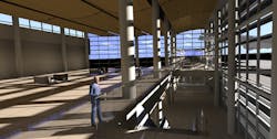
It is possible to combine radiosity and ray tracing to obtain the advantages of both approaches, something which is done by most commercial products (see Fig. 1).
Applications
Lighting design software can be applied anywhere electric lighting or daylight needs to be considered in terms of human activity. Examples include architectural interiors and exteriors, sports fields, roadways and tunnels, theatrical and concert venues, and industrial sites. As such, there are numerous units of measurement and metrics to be considered.
The most common measurement is horizontal illuminance–the amount of light (footcandles or lux) incident on a real or imaginary workplane in an office environment. It has been estimated that this accounts for perhaps 90% of the day-to-day use of lighting design software. Less common but still important is vertical illuminance, which determines, for instance, whether there is enough light to recognize faces on transit station platforms.
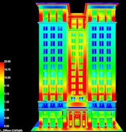
Other units of measurement include luminous exitance (lm/ft2 or lm/m2) and luminance (cd/m2) for exterior surfaces (particularly building façades and monuments), lighting power density (W/ft2) and Unified Glare Rating (UGR) values for interior electric lighting, illuminance uniformity gradients and coefficients for sports field lighting, small target visibility (STV), fitted target efficacy (FTE), and pavement and veiling luminance values for roadway lighting, daylight factors and LEED 2.1 criteria for architectural daylight design, and more (see Fig. 2).Radiosity-based calculations have the advantage in that once they have been completed, a virtual light meter can be placed and oriented anywhere in the environment. By comparison, ray-tracing-based calculations are limited to the user-specified viewpoint; choosing a new viewpoint requires repeating the lighting calculations, a process that may take minutes to hours to complete. For a typical large architectural project, the software has to iteratively calculate the inter-reflections of light between hundreds of thousands to millions of polygonal elements.
Architectural lighting designs usually have to satisfy a variety of municipal, state, and federal building code requirements, a process that is becoming increasingly complex with the adoption of energy conservation requirements such as the US Green Building Council's Leadership in Energy and Environmental Design (LEED) certification. This necessarily involves daylight, where the designer has to consider the time and date, geographic location, site orientation, and sky conditions derived from annual weather data.
This is the current state-of-the-art in lighting design and analysis software (see table). What is exciting is that the introduction of solid-state lighting and a renewed emphasis on daylight within the architectural community are bringing about major changes in the field.
Future directions
What may be surprising is that there is so little emphasis on color. While designers may specify the colors of opaque and transparent materials, this is mostly for generating photorealistic images for client presentation purposes, such as that shown in Fig. 1. For lighting designers, color has rarely been an issue with respect to design calculations.
One reason for this has been that lighting designers rarely had the opportunity to work with colored light sources. All lamps were considered "white" light sources. If colored light sources were encountered, they were almost invariably metal halide arc lamps with dichroic color filters intended for entertainment lighting. For white light sources, the only parameter of interest for colored materials was their grayscale reflectance.
The introduction of solid-state lighting nearly a decade ago changed all this. Multicolor LED-based luminaires with dynamic color-changing capabilities are now commonly seen in architectural and theatrical settings. These include white light luminaires with variable correlated color temperatures (CCTs) that enable the user to choose between "warm" and "cool" white light.5
Lighting design software developers have been slow to respond, but new features and capabilities are coming. These include full-spectrum analysis, where the red, green, and blue tristimulus values currently used to specify material colors are converted into equivalent spectral power distributions with 5 or 10 nm resolution. Combined with psychophysiological models of color perception such as the Bradford transform, this will enable lighting designers to accurately visualize how different material colors will appear when illuminated with light sources having different CCTs and Color Rendering Indices (CRIs).6, 7
The need to visualize dynamic lighting, including dimming and color-changing effects, is also being addressed. Most desktop and laptop computers today include graphics processing units (GPUs) to accelerate computer game graphics. This technology is currently being adapted for lighting design software, with lighting designers able to interactively tour their 3D virtual environments while watching the lighting dim and change color in response to user input, timers, and virtual occupancy sensors.
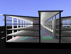
This technology will also enable a new approach to architectural daylight studies. Lighting designers currently have to perform hundreds to thousands of daylight simulations in order to perform an annual energy savings analysis. This makes it impractical or impossible to experiment with different daylight sensor positions, dimming control algorithms, and adjustable shading devices such as roller blinds. GPU-based lighting design software will enable designers to experiment with all these design options interactively, with annual daylight analysis results available in minutes rather than hours to days (see Fig. 3).Finally, the mainstream introduction of LED-based high-definition television and computer monitors with localized dimming capabilities has introduced professional lighting designers to high-dynamic-range imaging.6 With these displays and the appropriate lighting design software, it will be possible for designers to visually communicate their designs to the client.
Lighting design and analysis software currently meets the needs of professional lighting designers, but it is capable of much more. Lighting designers heard their clients when they said, "Forget the numbers! What will your design look like?" and progressed from numeric-only programs to architectural visualizations. The next generation of lighting design software will become the common tool of both lighting designers and architects, with the ability for all parties to both visualize and analyze both electric lighting and daylight designs.
REFERENCES
1. I. Ashdown, Radiosity: A Programmer's Perspective, Wiley (1994). (Freely available from www.agi32.com under "Support - Technical Documents.")
2. http://en.wikipedia.org/wiki/Radiosity_(3D_computer_graphics)
3. P. Dutré et al., Advanced Global Illumination, A.K. Peters (2006).
4. http://en.wikipedia.org/wiki/Photon_mapping
5. I. Ashdown et al., "White-light LEDs range from 'warm' to 'cool," Laser Focus World, 42, 5, 73-77 (2006).
6. E. Reinhard et al., High Dynamic Range Imaging, Second Edition, Morgan Kaufmann (2010).
7. M. Rea, Ed. IESNA Lighting Handbook, Ninth Edition, Illuminating Engineering Society of North America (2000).
Ian Ashdown is president of byHeart Consultants Limited, 620 Ballantree Road, West Vancouver, BC, Canada V7S 1W3; e-mail [email protected]; www.helios32.com.


