Software conquers design and analysis of backlit LCDs
R. JOHN KOSHEL
Edge-lit backlit liquid-crystal displays (LCDs) are used in products such as laptops, cell phones, and PDAs because they provide thin, small-volume solutions. Unfortunately, their inherent complexity makes them difficult to design. The goal of a good display design is high transfer efficiency, defined as the visible light flux emitted by the source compared to that emitted by the display output aperture. Secondary to that goal is high luminance uniformity—luminance is the spatio-angular distribution measured in nits, or lumens/meter2/steradian. New features in software tools such as TracePro help keep track of these goals while reducing design complexity.
A good design will balance high transfer efficiency and luminance uniformity, and will minimize spectral variation across the display. In addition, the design must consider the viewing angle of the observer, which is typically narrow in the vertical range and broader horizontally. However, cost is often the most important factor to the manufacturer and must be considered against the rest of the objective criteria.
The limits of the human eye play a crucial role in display design. The instantaneous dynamic range of the human eye is about 2.4 orders, while the full range is 7 orders. Studies have shown that observers prefer a slowly varying, minimum-to-maximum illuminance (lumens/m2) ratio of 70% across the width of a typical office desk. Thus, the nonuniformity across the display should be at most 30% (0.15 orders). Ideally, a 20% variation will take into account acceptable tolerance levels.
Display components
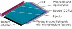
An LCD light engine comprises the light source, injector, lightguide, microstructure lightguide features, back reflector, and films such as diffusers or brightness-enhancement films (BEFs). The most effective design incorporates each of these components, as well as the polarizers and liquid crystal, which can affect performance (for example, causing undesirable moiré patterns).
The first component to consider in the LCD design is the light source. Until recently, cold-cathode fluorescent lamps (CCFLs) were the primary source used in displays. But white-light LEDs are increasingly used because they have a higher electrical-to-optical efficiency, a larger color gamut, and enable “instant on.” They also eliminate mercury, an environmental pollutant found in CCFLs.
The second component is an injector—an optical device used to couple the light from the source to the lightguide. The injector for a CCFL is a trough reflector, either specular or diffuse. For LEDs, the injector can be as minimal as a simple recess in the lightguide to capture high-angle emission, typically made out of acrylic. A wedge-shaped lightguide frustrates total internal reflection (TIR) due to étendue considerations, causing light to be emitted from the two large faces of the lightguide (see Fig. 1).
Microstructure features placed on the bottom of the lightguide surface reduce the TIR while addressing luminance uniformity. In the past, these features were dots of paint on the lightguide. More recently, microstructure geometry is incorporated into the injection-molding process to reduce cost and fabrication time. The microstructures are either holes, which project light into the lightguide, or bumps, which project out of the lightguide. A diffuse or specular bottom reflector captures and recirculates any light that leaks out the bottom of the lightguide.
Various films, such as diffusers and BEFs, are often placed above the lightguide exit. Diffusers assist in providing additional homogenization of the luminance, but lead to additional losses. Brightness-enhancement films and polarization-preserving dual BEFs are increasingly being used to provide output in the desired angular range. These films are essentially extruded microprism structures that recirculate light back into the light engine until it is in the desired angular range, albeit with more loss.
Example design
As a design example, consider an edge-lit, backlit display with a flat, 4-mm-thick lightguide, five white-light LEDs, a diffuse back reflector, and a standard three-axis polish surface on each of the lightguide surfaces. For an unwedged lightguide, we only see leakage at the input face or due to surface roughness. The bulk of the light is trapped in the lightguide because of TIR. We add a wedge shape to the lightguide such that its thickness decreases to 1.0 mm at the edge opposite the input. To further enhance the display, we optimize the placement, size, and density of the microstructure features and add the 3M Vikuiti BEF-II model from TracePro’s library. The CAD design of the complex feature pattern can be handled by software such as Gtools from G2 Technologies of Taiwan.
Recently TracePro included the capability to import such optimized patterns. A new tool called Textured RepTile allows for arbitrary placement of parameterized microstructure patterns, including bumps and holes on a single surface and several types of microstructure geometries, such as spheres, prisms, and cones. This generality allows the designer to optimize the output luminance to obtain the highest transfer efficiency while approaching the goal of negligible nonuniformity.
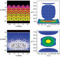
After optimization of the wedged design, a comparison of the illuminance and intensity with that of other designs shows that the wedged, fully optimized design returns the highest transfer efficiency of all the designs, with near uniform illuminance and an intensity that is symmetric in the horizontal direction (see Fig. 2). The transfer efficiency for a wedged design improves to 54.8% (from 0% for an unwedged design), and minimum-to-maximum illuminance ratio goes from 0% with an unwedged design to 80% for the wedged design fully optimized with components. The next step is to view the luminance, a complex process achieved by plotting the lit appearance.Software tools such as Textured RepTile greatly enhance the ability to handle complex patterns that incorporate millions of microstructure features. Such feature patterns can be developed in CAD programs such as GTools and then optimized in an iterative fashion to ensure high transfer efficiency, high illumination uniformity, and adherence to strict manufacturing demands. Lit-appearance modeling tools can be integrated into the design process, which is especially fortuitous for displays because simulated display images can be viewed in three-color renderings.
REFERENCES
1. M.S. Rea, editor, The IESNA Lighting Handbook Reference and Application, 9th Ed., IESNA, New York, NY (2000).
2. A. Arecchi et al., Field Guide to Illumination, SPIE Press, Bellingham, WA (to be published 2007).
R. John Koshel is senior staff engineer of Lambda Research, 25 Porter Rd., Littleton, MA 01460; e-mail: [email protected]; www.lambdares.com.

