Modeling Software: Understanding the Sagnac effect through ray optics simulation
It is now easier than ever to create high-fidelity numerical simulations of inertial navigation and attitude control systems of the type typically found aboard aircraft and spacecraft. One of the unique challenges of modeling an inertial navigation system (INS) is that the simulation domain often exhibits both translational and rotational motion, and this rotation can be pivotal to the system’s operation and performance.
Perhaps no device demonstrates the need to accurately capture noninertial motion of the simulation domain as well as the humble Sagnac interferometer. The basic operating principle of the Sagnac interferometer, the Sagnac effect, is also behind the operation of the ring laser gyroscope (RLG) and fiber-optic gyroscope (FOG)—devices that have become standard tools in defense and space travel. The RLG is both highly accurate and, because it doesn’t rely on moving parts as mechanical gyros do, relatively cheap and easy to maintain.
In its simplest form, the Sagnac interferometer has the following components: a light source, a beamsplitter to separate the light source into two distinct paths and to recombine them later, and a set of mirrors, typically two or three in total.
The beamsplitter and mirrors comprise a triangular or rectangular path that the light follows in both directions. Meanwhile, the entire apparatus (plus the aircraft or spacecraft it is onboard) also rotates at some angular velocity. By observing how light traveling along each distinct path interferes with the other, the angular velocity of the rotating system can be deduced to extremely high accuracy. Measuring these tiny rotations is a vital task in attitude detection and control.
Modeling light propagation in a rotating geometry
How does one predict the path of light in a rotating assembly of mirrors, prisms, and beamsplitters? First, let’s assume that the rotation is much slower than the speed of light (so we don’t need to delve too far into the theory of relativity), but still fast enough that we need to take the motion into consideration. At least two options come to mind:
1. Reformulate the equations for light propagation in a noninertial frame of reference, or
2. Rotate the geometry in real time as the rays propagate.
The difference is essentially one of carrying out the simulation in a noninertial or body-fixed frame of reference attached to the interferometer (1) or a space-fixed laboratory frame (2). Of these two possibilities, option (2) is much easier to implement, and so this is the approach we’ll take in modeling the Sagnac interferometer.
The COMSOL Multiphysics software is a particularly effective tool for modeling devices where the geometry moves or deforms, like the Sagnac interferometer and RLG, because the integration of a transforming geometry into the model is completely seamless. The treatment of deforming and moving geometries has always been held to an extremely high standard because of the diverse application areas that require this type of analysis, such as thermal stress, fluid-structure interaction, electrodeposition, multiphase flow, and piezoelectric devices, to name a few. Therefore, accurately tracing rays in a moving geometry can be as simple as entering a value of the angular velocity and then computing the ray paths.
The Sagnac effect: elementary theory
The easiest way to visualize the Sagnac effect is to imagine that light is constrained to move in either direction around the circumference of a circle—directed by a fiber-optic cable, for example. In Figure 1, light is released in either direction from point P0. The clockwise path is shown as a dotted line while the counterclockwise path is shown as a thick solid line. These are counterpropagating rays of light because they wrap around the circle in opposite directions.
If the rings were not moving, then the two light paths would cross once at the opposite side, and then a second time at the initial point P0. But suppose instead that the ring is rotating counterclockwise around its center with some angular velocity. If we then follow the motion of point P0 while the light propagates, we’ll find that it has reached a new position P1 by the time the clockwise light beam returns to it. And P0 reaches yet another distinct location, P2, by the time the counterclockwise beam returns to it. P2 is farther from P0 than P1 because the circle itself is rotating counterclockwise.
Formally, the Sagnac effect is more general than the example described above. The path the counterpropagating rays follow can be any shape, and the time delay between the two rays is proportional to the area enclosed by the loop. Furthermore, the rotation can be about any point, not just the center, and the same effect will be seen.
Ray optics simulation example
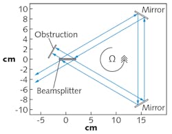
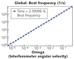
In this example, instead of a circle, the light now traces out the perimeter of a triangle, where the vertices are two mirrors and a beamsplitter (see Fig. 2).The two counterpropagating beams start out as one ray that passes through the beamsplitter. This produces two rays of equal intensity. At the instant they leave the beamsplitter, both rays have the same position and both are in phase. But because the mirrors are rotating, by the time the rays return to the beamsplitter, there is some optical path difference and thus a phase difference between them. From the phase difference we can then derive a beat frequency, which is easier to measure than comparing the optical path lengths directly.
Looking forward
The Sagnac effect is, at its core, a relativistic effect—but when the rotations involved are small compared to the speed of light, it can be accurately predicted using a ray-tracing simulation in a rotating geometry. This makes ray-optics simulation a viable tool for the analysis of inertial navigation systems like the Sagnac interferometer.
Realistic inertial navigation systems are much more complex than the basic arrangement of a beamsplitter with two mirrors shown in the previous example. Obviously, an external structure is needed to maintain the relative positions of the optical components. The INS doesn’t operate alone, but is instead mounted alongside other sensitive pieces of equipment in very limited space. The INS may also operate in a harsh environment where it may be influenced by outside structural, thermal, or electromagnetic phenomena. Because of these diverse physical phenomena, an uncoupled ray tracing analysis of the Sagnac interferometer or ring laser gyro is merely one step in the analysis. It should always be performed with the goal of a high-fidelity, coupled multiphysics simulation in mind.
About the Author
Christopher Boucher
Lead Developer
Christopher Boucher is a lead developer at COMSOL. He received his BS degree in aerospace engineering and physics from Worcester Polytechnic Institute (WPI) before joining COMSOL in 2012.


