Robert H. Gregory and John C. Hotchkiss
Selecting the right frame grabber for a particular scientific or industrial application involves more than just picking a board from a catalog. The most critical aspects to consider include front-end design, camera-control capability, and availability of software-development tools.
The single most important task that a frame grabber performs is converting analog video data to digital data that can be stored, manipulated, evaluated, and acted upon. Generally speaking, there are two classifications of commercially available frame grabbers: those designed for industrial and scientific applications and those designed for multimedia applications. Although many multimedia boards are promoted as being "universal" for all imaging applications, these two frame-grabber types cannot normally be used interchangeably. The goal for industrial and scientific frame grabbers is to perform the conversion operation as accurately as possible without altering the video data content. But the multimedia frame grabber's goal is to perform the conversion and, for aesthetic purposes, to alter the data to make it look more appealing.
Specifications and design criteria
The following specifications and design criteria must be considered when selecting a frame grabber for an industrial or scientific application.
Input filters. Chrominance filters, which are used on monochrome frame grabbers to remove color information from color video signals, allow for clean acquisition and more-accurate analysis. If the filters are not properly designed, however, they can remove additional image data that is necessary for accurate imaging. It is important, therefore, to use only high quality "notch" type filters so that bandwidth is preserved and only the color data is removed.Noise and conversion circuitry. Input and conversion circuitry can create spurious noise that alters the video data. Two noise specifications are important: integral nonlinearity and RMS (root mean squared) noise. Both of these are measured as LSB (least significant bit), which is represented as a part of the digitization accuracy of the gray-scale levels.
Integral nonlinearity represents the deviation of the gray-scale value that the board acquired from the actual gray-scale value of the image. RMS noise represents the spurious noise added by the board's circuitry. In both cases, the lower the value, the better the specification. Integral nonlinearity values of less than 0.5 LSB are considered excellent. RMS noise values of less than 0.7 LSB are considered very good, while RMS noise values less than 0.5 LSB are considered excellent.
Synchronization. When converting the incoming video data, frame grabbers must synchronize their on-board clocks to the timing stream of the incoming video signal. This process is accomplished via a PLL (phase lock loop) or a digital-clock-synchronization (DCS) circuit located on the frame grabber. The timing error measurement quantifying the error induced by the A/D clocking circuit is jitter. Typically measured in nanoseconds, jitter causes horizontal lines of data to be improperly aligned with each other, resulting in pixels that are not correctly positioned. This, in turn, alters the integrity of the video data.Since scientific and industrial applications require the greatest digitization accuracy and flexibility, the frame grabber should use a DCS circuit. For jitter specifications, ±6 ns maximum (±4 ns typical) is considered good; ±5 ns maximum (±3.5 ns typical) is considered very good; and ±4 ns maximum (±2.5 ns typical) or less is considered excellent.
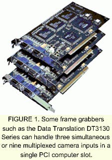
Aspect ratio. The ratio of the horizontal dimension of the image to its vertical ratio is termed its aspect ratio. As long as the image is acquired and displayed using the same aspect ratio, it does not matter very much what that ratio is. Shapes are not distorted—squares still appear square, and circles still look circular. Aspect ratio becomes important in certain processing operations, such as determining the area of a region by counting pixels, or in-group operations such as convolutions where a region of the image is being processed. In these operations, the user must compensate for pixels with an aspect ratio that is not 1:1. Aspect ratio also is important if the image must conform to a graphics standard. So if the application requires precise pixel measurements, the user must ensure that the frame grabber board provides square pixels or an aspect ratio of 1:1.Multiplex inputs. Often, there is a need to connect more than one video source to a frame grabber. Most frame grabbers have a built-in input multiplexer circuit, allowing the user to select one of several video sources. Depending on the application requirements, the user may need to acquire from multiple video sources simultaneously. In this case, a frame grabber must either have multiple simultaneously active input channels available, or the frame grabber software drivers must allow for multiple frame grabbers to be installed in the host computer and run in parallel to provide the channels needed (see Fig. 1).
Programming or flexibility. When nonstandard input sources are used (those that do not adhere to standard spatial resolution formats and/or video timing formats), a "variable-scan" frame grabber must be used. This type of frame grabber allows the spatial resolution as well as the pixel clock rate to be programmed, thereby allowing the board to be perfectly matched to the video source. When selecting a variable-scan frame grabber, the user should ensure that all of the programmable limits for both spatial resolution and pixel clock speed meet or surpass the specifications of the video source.Programmable gain and an adjustable input range (achieved by setting the A/D converter's offset and reference values) allow the user to digitize nonstandard video signals and video signals in low-light conditions. By using programmable offset, gain, and reference settings, the user can fine tune the input to exactly match the signal being supplied, resulting in more accurate data sampling.
Look-up tables. Often, frame-grabber boards provide look-up tables (LUTs). Two types are available: input look-up tables (ILUTs) and palette-matching look-up tables. Although they are similar in design, they perform different tasks. Input LUTs are format RAM that allow the user to change the pixel values of an image while it is in the digital domain prior to it being stored or displayed. Since it is much faster to perform this task using the frame-grabber hardware—as opposed to system software—this feature is very useful in high-speed inspection applications where image manipulation must be performed as quickly as possible.A palette-matching LUT is format RAM that allows changes to be made to the image while it is being displayed. By using a palette-matching LUT, the user can change the displayed image without altering the original ILUT itself. This feature is useful if the original image data must be left in its original form, but the displayed image data must be enhanced for ease of viewing.
Direct draw. Often, applications require live video (30 FPS) to be displayed with overlays (such as on-screen graphics) to highlight certain aspects of the image. Some frame grabbers supply on-board display circuitry to accomplish this task. A better solution is Microsoft's Direct Draw Interface standard, which allows for smooth flowing, flicker-free live video display, as well as live, animated, non-destructive overlays. This technique eliminates the need for additional expensive display hardware on the frame grabber, which often cannot match the performance of the PC graphics adapter.
Scaling and cropping. Some applications require images to be cropped or resized to fit within particular window boundaries on the image display. Scaling is typically performed using one of two methods—decimation or interpolation. Decimation involves the process of discarding lines and/or pixels to reduce the size of the image, while interpolation uses an averaging technique among the lines and pixels. Although both techniques are useful, of the two, interpolative scaling retains more image detail as the image is scaled.
Image cropping (also known as clipping) allows for a region of interest (ROI) to be selected out of an overall image. Image data within the region is transferred to the host computer while the data outside is discarded. Often used in high-speed applications, ROIs allow for faster image transfer and reduced processing time.
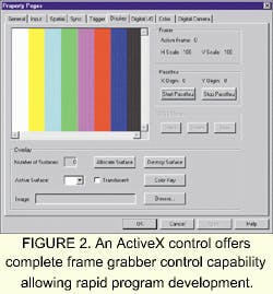
Camera control. Typically, the camera generates sync signals that are embedded in the video data stream. The frame grabber then strips them out and uses them to "lock" its internal clock to that of the cameras. In some applications, however, additional control over the timing of the camera or the frame grabber is required. Frame grabbers that provide separate H sync, V sync, and pixel clock input and output signals allow for added camera configuration flexibility. Other control signals such as camera exposure and reset signals provide even greater camera control.I/O channels. If the frame grabber has digital input and output (digital I/O) channels, the user will be able to monitor and control external devices or peripherals without having to install a separate digital I/O board. This feature eases integration, since there are no additional drivers to load, and the commands used to operate the digital I/O are available through the frame grabber's command set.Supporting software. Most frame grabbers include software—as example programs or mini-applications—which helps the user get the device up and running quickly and to give examples on how to integrate it into the application. Such programs also act as diagnostics to verify overall frame grabber operation. Mini-applications represent a step up from example programs. Not only do they allow a multitude of board features to be used, but often they provide the ability to save and load image data in a variety of file formats. Development software. Development time and time-to-market are always concerns when developing an application, especially when hardware integration is required. To make the frame-grabber implementation task easier, the user should ensure that the proper software tools and target operating system support are available. If the user is creating an application program in C, the frame grabber should include drivers for the target operating system as well as a software developer's kit, which will make it easier to integrate the frame grabber into the application. When creating an application program in Visual Basic or Visual C++, the frame grabber should have an ActiveX control (see Fig. 2).If there is a need to upgrade or change to another type of frame grabber, or if multiple types of frame grabbers are used in the same application, all the frame-grabber drivers must be written using the same modular hardware-independent API. This not only allows the user to use common command and function calls for all of the boards, but also allows easy migration from one frame grabber to another without having to rewrite code. When using multiple frame grabbers, the drivers must support running multiple boards—of the same and different type—in the same host system.
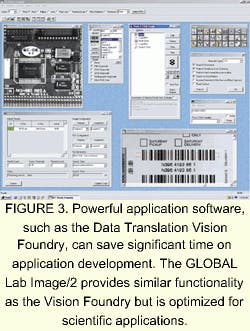
Application software. Compatible application software can reduce or eliminate the need for complex software development. If the frame grabber is supported by powerful machine vision or scientific imaging application software, the user can save a significant amount of time in bringing the project to completion (see Fig. 3).All frame grabbers are not the same; nor are all frame grabbers equally suited for all jobs. Most industrial and scientific applications require a frame grabber with features and software support designed for a particular task, whether it be speed, accuracy, or multiple inputs. By following these guidelines for selecting both frame grabber hardware and software, the user can quickly and easily match the best frame grabber for the application at hand.
ROBERT H. GREGORY is senior product manager and JOHN C. HOTCHKISS is product manager at Data Translation Inc., 100 Locke Dr., Marlboro, MA 01752.


