Coupling macro and micro codes enables integration ofsubwavelength features
Joe Shiefman
Interest has been growing in the ability to model optical
systems that include subwavelength structures at one or more points in the system. As efforts continue to extend the limits of optical resolution and as more applications for new types of nanostructures are developed, the value of coupling macro and micro optical software increases. This approach has applicability in a wide
variety of fields, including semiconductor lithography, optical data storage, telecom, biophotonics, and metrology systems.
Most optical-system software codes perform field propagation based on classical, scalar diffraction theory. These codes are very good at modeling propagation through standard optical components, but their accuracy degrades and ultimately fails as feature sizes approach and then fall below the wavelength of light. Correct propagation through subwavelength structures requires consideration of the coupling of the electric and magnetic fields as described in Maxwell’s equations, along with the appropriate constitutive relations.
One technique for accurately modeling propagation through subwavelength structures is the finite-difference, time-domain (FDTD) method, which discretizes Maxwell’s equations by using a central-difference operator in both time and space variables.1 The electric and magnetic fields propagate in discrete time steps (hence time-domain). Unfortunately, these techniques require large computer resources and are very slow. As such, they cannot practically model an entire optical system.

Therefore, to accurately model optical systems that include subwavelength structures, it is necessary to couple the FDTD software to optical-system software. In recent years, much work has been done to model these types of systems using a combination of scalar and FDTD techniques.2 Each portion of field propagation is performed in the appropriate software type, passing the field values to the other type of software for continued propagation.
Conceptually all that is necessary to exchange field values between scalar and FDTD software is for each code to be able to import and export field files from and into the other code. In practice several issues must be considered to ensure that values are exchanged correctly.
General issues
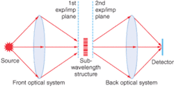
Five steps are involved in modeling a typical optical system, containing a subwavelength structure (see Fig. 1): propagate field through the optical system using scalar techniques stopping at a plane in front of the sub-wavelength structure; transfer the field to the FDTD software; propagate fields through the subwavelength structure using the FDTD method; transfer field back to the system software; propagate field through remaining system.
The two major issues in exchanging and propagating fields between the two software types are transferring an accurate, complete description of the field and changing the sampling density of the field to be appropriate for further propagation inside the other code.
Typically, fields are transferred in a plane within a homogeneous, isotropic medium. In addition to containing the complex field values (Ex, Ey, Ez, Hx, Hy, Hz) for every pixel in the plane, the field files must also specify the index of the medium in which the field is immersed, the radiation wavelength, the number of pixels, and either the pixel sizes or the total window size.
Field files must also describe the location to place the field within the coordinate system of software into which it is imported. This description is simplified if the two codes share a common coordinate system. Otherwise a coordinate transformation will be required. In addition, field files must contain the direction in which to propagate the field. The required information can be contained inside the exported field file or the software user can input it
manually. The field exchange process can be described in terms of four types: exporting fields from systems software; importing fields into FDTD software; exporting fields from FDTD software; importing fields into system software.
Exporting from system software
When the software user chooses to export a field file from a system software code he or she must specify the parameters that define this exported field. In addition to the general parameters listed in the section above, the user must name the file that will be imported into the FDTD code, and specify the coordinates of the location from which the field is to be saved. Also, most system codes contain values of the electric field, but not the magnetic field required for the FDTD software. Fortunately the magnetic field can be derived from the electric field. Because the values of the magnetic field are not required until the propagation takes place inside of the FDTD code, this procedure can be performed inside either software code or even offline.
Importing into FDTD software
To import the field into the FDTD code the user must specify that the
analysis source to be propagated will be an imported field file of a given name. The user must specify where to locate the imported field in the coordinate system of the FDTD software. The starting location of the field relative to the subwavelength structure should be the same as it was when the field was saved inside of the system code. Because the pixel dimensions in FDTD software are typically smaller than those used in the system code, the FDTD code will typically interpolate field values to fit the imported field into its spatial grid.
Exporting from FDTD software
Converting the time-dependent field values in the FDTD code into the time-independent field values required for export to a system code is accomplished by a discrete, temporal Fourier transform of the FDTD field values. Depending on the optical system being modeled, the field saved for export can be either a field reflected from the structure or a field transmitted through the structure.
Importing into systems software
Typically the field that has been saved from the FDTD software has a finer resolution than is practical for propagation in a system code. Therefore, the imported fields must be spatially filtered to remove evanescent field components. If one were to directly fit data imported from FDTD code to a coarser grid without first spatial filtering, it would be equivalent to sampling below the Nyquist rate and would cause aliasing errors in any further propagation. After removing the evanescent components, the sizes of the window and pixels used to describe the field can be rescaled to values more appropriate for propagation in the system software.❏
REFERENCE
1. K.S. Yee, IEEE Trans. Antennas and Prop.14, 302 (1966).
2. M. Mansuripur, A.R. Zakharian, J.V. Moloney, Opt. & Phot. News 3, 56 (2003).
JOE SHIEFMAN is an optical engineering consultant and the North American sales and support representative for DIFFRACT and Sim3D_Max optical software, 2530 N. Falling Water Ct., Tucson, AZ 85749; e-mail: [email protected]; www.shiefman.com.