For many conventional optical systems, such as a typical camera lens, ray tracing based on the geometrical concepts of Snell's law provides an excellent simulation method for system design. In many other systems, however, of which optical telecommunication systems provide an increasingly important example, diffraction effects become significant enough that simple ray tracing no longer suffices. This article looks at two alternatives provided in commercially available optical design software.
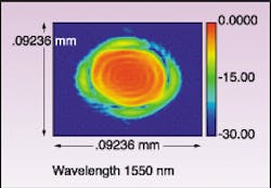
A classic optical telecom design problem might be posed by optical switching using MEMS devices, according to Tom Bruegge, chief engineer for photonics software at Optical Research Associates (ORA; Pasadena, CA). "You might have an array of small mirrors that steer small beams onto another array that's a significant distance away," he said. "This distance could be inches, it doesn't have to be feet (see Fig. 1). But if the wavelength of the light is, as in telecom, on the order of 1.3 to 1.5 µm, and the MEMS mirrors themselves are typically on the order of 100 µm, then you will have significant diffraction effects."
Free space propagation
A widely used approach to these types of problems is to use diffraction-based algorithms for free space beam propagation, according to Bruegge. This is the approach incorporated into ORA's Code V software. The technique uses either a Fraunhoffer or Fresnel algorithm to simulate beam propagation, with the choice between these two algorithms based largely on the Fresnel number of the propagation step.
"The Fresnel number indicates how close you are to the far field," Bruegge said. "It's a function of the distance you propagate, the wavelength of light and the diameter of the beam. For a small Fresnel number you're getting close to the far field, and for a large one you are in the near field, basically."
Roughly speaking, if the Fresnel number is smaller than 100, diffraction effects will be significant enough to use either the Fraunhoffer or Fresnel algorithms, Bruegge said. Also as a very general guideline, when the Fresnel number falls below one, the appropriate propagation method would be to use the Fraunhoffer propagation method. An example of this would be propagating a collimated beam a long distance into the far field.
The Fraunhoffer algorithm performs a Fourier transform of the input beam. And that gives the beam on the output surface directly, because the intensity of the beam on the output surface is proportional to the Fourier transform of the input beam squared.
For larger Fresnel numbers, the simulation moves closer into the near field and the Fresnel propagation method performs a linear filtering operation in which the input wave is decomposed into its plain wave components and then each of those plain wave components has a different phase shift.
An initial Fourier transform provides a plane wave representation of the optical field that can be propagated to the destination and then transformed back into the optical domain. A variation on the Fresnel algorithm is also available to deal with convergent or divergent propagation between concentric spheres.
Gaussian beam superposition
The ASAP software offered by the Breault Research Organization (BRO; Tucson, AZ) takes a different approach—Gaussian beam superposition—to modeling diffraction.
Instead of decomposing an optical field into a plane-wave spectrum using a Fourier transform-based algorithm, this software describes the optical field using Gaussian beams, according to Robert Upton, an optical engineer at BRO. For example, a truncated plane wave might be represented by a summation of about 500 or more Gaussian beams. And those Gaussian beams would be distributed spatially across the front of the plane wave.
"This method simulates wave propagation by tracing rays," Upton said. "You can describe each Gaussian beam by means of tracing five rays in three dimensions." The five rays consist of a base ray, which describes the direction in which the Gaussian beam is traveling; two parabasal waist rays (around the base ray), one for the z-y and one for z-x; and two more parabasal divergence rays for the diffraction angles in the z-x and z-y planes.
Simulations using the Gaussian method, even in optical systems with significant diffraction effects, basically boil down to ray-tracing calculations, which extends the applicability to scalar wave fields, Upton said.
"It's not limited to just Gaussian beams coming from lasers," Upton said. "You can simulate plane waves, spherical waves, waves with funny phases in them, whatever. It's quite arbitrary in that sense."
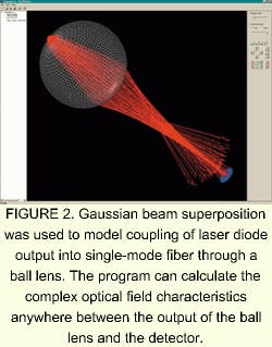
When the system components being modeled are relatively large compared to the wavelength of light, the Gaussian beam method can simulate telecommunication-component optical and mechanical geometries (see Fig. 2). Diffraction gratings are handled macroscopically with the grating equation and not by constructing the small structure of the grating. Apertures are handled with a special decomposition technique instead of simply "clipping" Gaussian beams. But the Gaussian method also has limitations for situations in which aperture dimensions or object spatial frequencies are near to or below the wavelength of the light traveling through them.Purely diffractive phenomena with no equivalent ray trace model, such as propagation in a single-mode fiber, cannot be modeled within a traditional Gaussian algorithm. In such cases the simulation must go out of the Gaussian mode temporarily to simulate (in this case) the single-mode fiber, either with a finite-difference, beam-propagation method within the software, or to an external simulation program. To facilitate the latter, the ASAP program provides "hooks" to interface the program with arbitrary fields and decompose them into Gaussian beams, Upton said.
For more information on other companies offering optical design software, see the Laser Focus World Buyers Guide 2001.
About the Author
Hassaun A. Jones-Bey
Senior Editor and Freelance Writer
Hassaun A. Jones-Bey was a senior editor and then freelance writer for Laser Focus World.

