SOFTWARE: DESIGN FOR MANUFACTURING: Adaptive software eases camera lens-to-sensor alignment

JUSTIN ROE and AARON ISRAELSKI
Driven by recent advances in and demands for mobile technology such as smart phones and tablet computers, as well as growth in medical device and automotive applications, camera module demand is growing. These compact camera modules—with more than 1.5 billion units to be produced in 2013—are also advancing in capacity and capability. However, in order to reach their full potential and produce high-quality images that are also highly focused, they must be assembled with precision. To best approach the increasing challenges of the industry, the software and hardware aligning and assembling these cameras must work in unison to create a product that is assembled both accurately and efficiently.
Camera alignment basics
Traditionally, the lens barrel of a camera was manufactured with threads so that it could be attached to the sensor using a screw-in method that allows for alignment in one degree of freedom (z) while adjusting the distance of the lens from the sensor. This method often fails in small-scale high-megapixel camera modules; that is, if the lens or sensor is embedded at an angle, and only the center of the image is focused, the edges of the image will be noticeably out of focus.
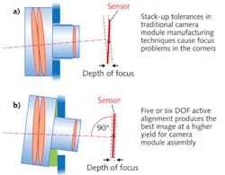
By aligning the lens in five or six degrees of freedom instead of just one, the lens may be positioned with near-parallel precision to the image sensor (usually within 0.01 degree), resulting in a uniformly focused image across the entire active area of the sensor (see Fig. 1).
The six degrees of freedom are based on aligning the object relative to three perpendicular axes: x, y, and z. The camera lens can be moved forward or backward (y), up or down (z), and left or right (x), combined with rotation around the three perpendicular axes—usually termed pitch, yaw, and roll (rotation indicated by θ). Together, these movements constitute the six degrees of freedom x, y, z, θx, θy, and θz.
Focus quality is determined using real-time measurements of the modulation transfer function (MTF) at a given lens position. By controlling tip and tilt and collecting MTF data during through-focus sweeps, one can determine the optimal plane in pitch and roll for the lens; the optimal plane being that alignment position where performance is optimized for off- and on-axis focus.
The MTF is derived from spatial frequency response (SFR) data complying with the ISO 12233 standard concerning resolution measurements for electronic still-picture cameras. The MTF can be calculated and reported either in cycles per pixel as a function of a user-configurable modulation percentage, or as a modulation percentage as a function of cycles per pixel specified by the user. The ability to determine MTF in this manner provides substantial flexibility, allowing for correlation with MTF values from the system to external measurement data.
Alignment along the x and y axes combined with image data from the sensor allows alignment software to determine and correct for optical x-y centration error. For multilens applications such as three-dimensional (3D) or other multilens cameras, the sixth adjustment axis (yaw) can be used to simultaneously align the multiple optical axes of the lenses.
As camera module quality improves and manufacturers feel pressure to produce newer, more complex camera modules at increasingly fast speeds, the software that aligns the lens to the sensor must be more exacting, requiring significant new real-time analysis, while at the same time keeping manufacturing throughput high. In response, Kasalis developed intelligent software—its Adaptive Intelligence Suite—for its Pixid camera assembly systems that uses real-time feedback from the manufacturing process to increase camera performance while also reducing cycle time.
Adaptive Intelligence alignment benefits
To maintain high performance while minimizing size, weight, and power consumption of the camera, the alignment component is crucial. If camera modules are optimally focused across the entire image area using six degrees of freedom, every pixel in the sensor delivers the best possible image focus. Unlike traditional passive assembly processes, active alignment is an assembly process whereby the position of the lens is determined using acquired images across multiple regions from the camera's image sensor to ascertain the lens position yielding the best possible focus.
Beyond high performance, assembly speed is important to camera manufacturers. Software is the solution to obtaining high accuracy while increasing assembly speed and throughput. Adaptive Intelligence software adapts and improves its movements based on trends identified in previously aligned camera components, streamlining the alignment process and adapting it to each customer's own type of camera module and its performance trends.
By using a control computer with multiple processor cores, it is possible to calculate the MTF results for a camera while simultaneously analyzing other camera metrics and the historical trends and variances. From this current and historical data, the system can adapt to continually trade off between precision and cycle time, increasing precision where variance is great, and increasing process speed where variance is lower. For most camera modules, an alignment time of 4 to 5 s may be realized using our optimization software. The alignment time combined with other processes such as component curing and module testing results in a throughput of up to 240 lens-to-sensor units per hour.
Step-by-step intelligent alignment
First, an adhesive is dispensed and applied to the image sensor or sensor housing; second, the machine aligns the lens to the image sensor in five or six degrees of freedom; third, the adhesive is cured with ultraviolet (UV) light; fourth, the collected data is fed back into the software to improve upon its alignment process control.
The Adaptive Intelligence Software processes information collected from machine-vision functions, the active alignment process, post-attach data, and yield trends. Once the data are processed by the software system, the algorithm for aligning the camera lens to the sensor is altered to more closely reflect what has been learned from the collected data as part of a step-by-step, iterative alignment process.
Machine-vision data include trends in manufacturing tolerances and identification of batch-to-batch variation that can impact the assembly process. For example, using machine-vision guidance, the system's dispense module can identify the appropriate datum for the adhesive dispense pattern for a given image sensor or image sensor housing to accommodate positional variation due to component tolerances. Furthermore, using the same inspection system that is built into the dispense module, post-dispense inspection can be used to verify the accuracy and quality of the adhesive dispense pattern. Based on this inspection, the software can automatically recognize whether the quality of the adhesive dispense pattern is within configurable limits and automatically adjust dispense parameters if needed to improve the yield of subsequent assemblies.
Active alignment involves moving the lens in free space in five or six degrees of freedom while measuring focus quality at various points across the imaging area in order to determine the optimal tip/tilt, focus (z), and x-y position for optical centration. The final lens position is based on a number of factors such as step size, initial placement position, and thresholds for determining optimal focus quality. By monitoring trends in the focus performance of the lens as a function of position, the Adaptive Intelligence software automatically adjusts process parameters to improve both the quality of completed camera modules (resulting in higher yield) and the speed of the alignment (resulting in higher throughput).
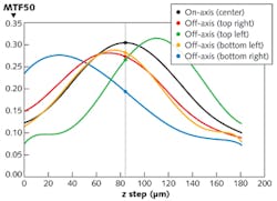
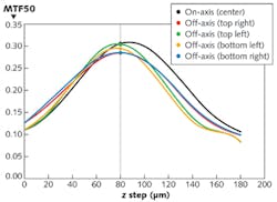
Post-attach data are gathered after the active alignment process and the lens fixed in place relative to the image sensor using adhesives that can be cured—typically using UV light. Given the chemical composition of many adhesives, it is common to see a small amount of volumetric shrinkage that occurs when the adhesive is cured. While this shrinkage is typically on the order of only a few microns, it may be enough to adversely affect the focus performance of the camera module. As such, prior to bonding the lens in place by initiating the cure with UV light, the lens is typically moved in the opposite direction from that in which the shrinkage would occur to compensate for the effect of the lens movement due to the adhesive shrinkage.Active alignment in five or six degrees of freedom corrects for tip and tilt to optimize the focus performance of a camera module in both the center and the corners of the image. The alignment process may be configured to optimize focus for 1) on-axis performance, 2) off-axis performance, or 3) overall performance (see Fig. 2). When manufacturers are assembling hundreds of thousands or millions of camera modules per month, adding dynamically adaptive software to the active alignment capability makes a significant and positive impact on operational efficiency and yield (see Fig. 3).
Justin Roe is president and Aaron Israelski is director of business development for Kasalis, 1 North Ave., Suite C, Burlington, MA 01803; e-mail: [email protected]; www.kasalis.com.

