SOFTWARE & COMPUTING: BEAM ANALYSIS: The basics of Gaussian beam decomposition
RICH PFISTERER
Discussed in the literature since the 1940s and well-established in computational form since the mid-1980s, Gaussian beam decomposition is a powerful technique currently available in optical software packages from three mainstream commercial companies, who offer it as an alternative to the more traditional Fourier-based propagation techniques for calculating the optical field in an optical system. Gaussian beam decomposition brings together elements of physical and geometric optics in a rather unexpected way, but its capabilities and limitations should be well-understood before the method is applied.
Beam basics
Propagating an optical field through an arbitrary optomechanical system is, in general, a difficult computational problem, particularly if the field is clipped by limiting apertures located along the propagation path. The classic approach is to represent the optical field by a complex array (real and imaginary data representing amplitude and phase) and to propagate this field via various types of near-field and far-field Fourier-transform-based propagators.
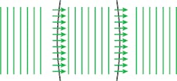
This technique is straightforward until the optical field encounters a lens or mirror. In 1970s-era propagation software, the optical field was simply multiplied by a complex transmission function representing the optical element—a poor approximation to reality especially if the surfaces were aspheric. In more modern software such as CODE V (from Optical Research Associates; Pasadena, CA) and ZEMAX (from Zemax Development Corp.; Bellevue, WA), the optical field is converted into a distribution of rays at each surface. The rays are traced through the surface, and then turned back into an optical field (see Fig. 1). This method does a much better job modeling nonparaxial surfaces.
If geometric rays are being used to properly ray trace through optical surfaces, it would certainly be convenient if the designer did not have to convert the optical field into a distribution of rays at each surface and then reverse the procedure after refraction/reflection. It would be even more convenient if they could describe the initial optical field with a distribution of rays and do the conversion from rays to optical field at the end of the ray trace. This can certainly be done but not without first making a detour.
Gaussian beam decomposition
The basic idea behind the Gaussian beam decomposition technique is to synthesize the desired optical field using a basis set of Gaussian beams, propagate these Gaussian beams through the system, and then reconstruct the optical field by coherently adding the individual Gaussian beams. While this sounds like a very indirect way of propagating an optical field, it is more straightforward to implement than one might think.
What is so special about Gaussian beams and why would they be considered useful as a basis set? Remember that the Fourier transform of a Gaussian function is another Gaussian function, and so the functional form of a Gaussian beam does not change during propagation (compare this to a plane wave that becomes an Airy function if propagated to the far-field). Consequently, if you start with a collection of Gaussian beams, you will finish with a collection of Gaussian beams after propagation through the system.
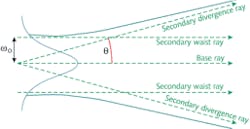
How are Gaussian beams propagated? Back in 1968, Jacques Arnaud at Bell Labs had the idea that Gaussian beams could be represented and rigorously propagated using geometric rays and he called this idea “complex ray tracing.”1-3 His concept was to surround the “base” ray (the central ray of the beam or, in other words, the ray that is typically traced in optical software) with a collection of secondary or “parabasal” rays.
There are two types of secondary rays: “waist” rays and “divergence” rays (see Fig. 2). The waist rays are initially parallel to the base ray but displaced laterally by the beam waist semi-diameter. The divergence rays are initially located at the center of the beam waist and are asymptotic to the far-field diverging spherical wave.A single Gaussian beam can, at best, acquire and represent quadratic phase; it can be traced along the axis of a system containing only focus error and represent the entire aberration content of the optical field at the image plane. However, in the presence of higher-order aberrations (such as spherical aberration), it takes several Gaussian beams—each representing a quadratic “piece” of the wavefront—to describe the entire wavefront. Therefore the aberration content of the optical system is significant when deciding how many Gaussian beams are required to synthesize the initial field.
Many inexperienced users tremendously over-sample the initial field for fear of missing something; but over-sampling has an unfortunate consequence. The construction of the secondary rays is based upon the inter-beam spacing and the wavelength; in particular the angle of the divergence rays is computed from the classical expression for Gaussian beam divergence tan θ = λ/πω0, where λ is the wavelength of the Gaussian beam and ω0 is the beam waist semi-diameter. If the inter-beam spacing related to ω0 is very small, the divergence rays, well … diverge, and may violate one of the several ray-tracing rules required by the implementation.
Since the technique is ray-based, aspheric, toroidal, and other special optical surfaces do not require any special handling; they are simply ray-traced. In addition, since each Gaussian beam is independent of every other, it does not matter if the beams propagate along different trajectories or even encounter different sequences of surfaces. This makes the technique a natural solution to the problem of coherent propagation through a nonsequential optical path or multiple-beam interference calculations.
Cautions
The major weakness of the Gaussian beam decomposition technique is that hard apertures can require special handling. When a Gaussian beam is clipped by an aperture, the algorithm requires that a new basis set of Gaussian beams be synthesized to describe the diffraction. Depending on the wavelength of the beam and the dimensions of the aperture, several hundred to several thousand new beams must now be created and ray-traced. This is usually handled by the software, but the impact to the user is a more time-consuming ray trace and ultimately the synthesis of the final optical field.
No one propagation algorithm works for every possible situation and so software developers strive to provide their users with useful and productive options. Gaussian beam decomposition would likely be the wrong tool for propagating a field through a sequential optical system with numerous limiting apertures. But in the case of a nonsequential system containing beamsplitters and complex optical surfaces, it might just be the answer the optical engineer is looking for.
REFERENCES
1. J. Arnaud, Applied Optics 24, 4, 538–543 (February, 1985; initially issued as an internal Bell Labs memorandum dated October 10, 1968).
2. A.W. Greynolds, “Propagation of Generally Astigmatic Gaussian Beams Along Skew Ray Paths”, Proc. SPIE, Current Developments in Optical Engineering and Diffractive Phenomena 560, 33–50 (1985).
3. R. Herloski et al., Appl. Opt. 22, 8, 1168–1174 (April 1983).
Rich Pfisterer is president of Photon Engineering, 440 South Williams Blvd., Suite 106, Tucson, AZ 85711; e-mail: [email protected]; www.photonengr.com.


