Interferometry: Tradeoffs in fixed vs. continuous-zoom interferometry factor into optics test optimization
ERIK NOVAK and EDGAR SCHROCK
The laser Fizeau interferometer is a powerful workhorse for testing the surface parameters and transmitted wavefront quality of all types of optics, for several key reasons. First, accuracy: since the test and reference beams travel through exactly the same optics, errors from the instrument itself are minimized, maximizing accuracy. Second, scalability: such systems are readily scalable via beam expanders to very large apertures—a Fizeau interferometer can be kinematically mounted as the main measurement engine for optical systems up to 24 inches in diameter, eliminating the chore of realignment. And finally, versatility: Fizeau interferometers are amenable to using either flats or spheres as the reference surface, allowing the testing of concave and convex lenses, prisms, and flats with equal ease.1
Several major advances in Fizeau interferometry have taken place over the last two decades—notably, dynamic interferometry, high-resolution detectors, and modified-coherence-length sources.
Dynamic interferometry—instantaneous acquisition of surface data in a single frame of interference fringes—has transformed optical testing by allowing snapshot measurements that are immune to vibration and motion. This eliminates the need for optical tables and permits measurement over very long distances, as in the case of testing large telescope mirrors. Dynamic systems have two primary types: on-axis (polarization-based) and off-axis.
High-resolution detectors have decreased considerably in both size and cost over the last few decades and are now common in most commercial interferometer systems. The increased spatial sampling of such detectors has created systems that tolerate higher slope changes, enabling measurement of a greater range of more dramatically curved optics.
Modified-coherence-length laser sources have been used to effectively separate out the interference of test and reference beam components. By separating them, both the test and the reference beams can remain on-axis, and these interferometers retain the common path cancellation advantages of the Fizeau configuration. The interferometer isolates and measures any surface that is substantially normal to the optical axis of the cavity. Stray light interference is also substantially reduced because of the short coherence from the source.
The most advanced modified-coherence-length systems include Surface Isolation System (SIS) modules that allow for measurement of plane-parallel optics with no issues from multiple surface reflections. An SIS module consists of a short (around 150 µm) coherence laser source, with an adjustable mechanism controlled to path-match the source with the external cavity separation between the test and reference optics. Once path-matched, the reference beam is coherent with the test beam, producing the interference fringes necessary for data acquisition.
One challenge with such general-purpose instruments, however, is that no one system can be perfect at everything. Laser Fizeau systems commonly are sold with apertures in one of two sizes: 100 mm or 150 mm. However, many optics are much smaller than this, and thus do not fill the entire field of view.
Aligning such small optics can sometimes be difficult, and the number of measurement pixels across the optic may be disproportionately small; for example, using a 100 mm aperture and a 1 × 1k pixel camera, a 10 mm optic will only have 100 pixels across its diameter. Being unable to increase magnification of the surface under test (that is, to optically zoom) limits the number of pixels present on the surface, preventing the user from measuring details of interest in a subsection of the optic under test.
Zoom interferometry considerations
While 100 pixels may reveal the overall shape of an optic, certain wavefront features may not be readily measurable, considering that high-performance systems increasingly try to limit mid- and high-spatial-frequency structures to improve image quality. Optics manufacturers using advanced diamond-turning techniques might feel the issue most acutely, as low resolution would tend to blur out tiny features like turning marks. Three approaches exist to address this problem: discrete-, digital-, and continuous-zoom interferometry.
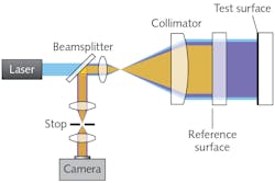
To understand the approaches, it is important to first review the Fizeau architecture (see Fig. 1). Consisting of a light source, expansion optics, and imaging optics, the expansion optics are dual-use—they expand the beam but also serve as the first stage of the imaging system. Thus, the quality of the expansion optics (front end) and the imaging optics (back end) determine the overall imaging capability. Ideally, both the expansion optics and imaging optics in the complete system are high quality and matched to offer pixel-limited imaging, but this is not always the case.
Good optical designs for Fizeau interferometers should consider retrace performance, which is caused by the wavefront distortion that occurs when the test beam returns at an angle with respect to the reference beam. Ideally, the test beam will only experience very small aberrations as it is tilted off-axis, resulting in small retrace errors (<1/10 wave). Low retrace error is particularly important for measuring non-null optics, such as aspheres, or spherical optics that are not at best focus. Off-axis (or spatial carrier) dynamic systems are particularly sensitive to retrace error and require special design of the illumination and imaging optics.
Digital zoom
A convenient method to achieve zoom without losing light and yet preserving high-quality imaging is the use of high-resolution detectors such as a 2.4 × 2.4k sensor, and a digital zoom approach. Although a digital zoom merely stretches the existing pixels for display purposes and does not provide additional sampling across any given distance, the capability of expanding key features on the display screen makes observing measurement artifacts easier.
By using very high-resolution detectors, considerable digital zoom can be used while still offering good spatial resolution. For example, 6 Mpixel cameras available in the 4D Technology (Tucson, AZ; a Nanometrics business) AccuFiz Fizeau line offer very good imaging capability and can be digitally zoomed by 10X without noticeable pixelation artifacts.
The advantage of digital zoom is that the measurement quality is not compromised in any way and the imaging optics can be designed to optimize imaging and retrace while minimizing the number of optical surfaces that can lead to stray reflections and artifacts—yet the measurement itself has the same sensitivity and detail, even though the image on the screen is larger. By zooming on the screen, the user is simply looking at an unchanged, smaller subset of the whole measurement field.
Step-wise: discrete zoom
The problem of achieving variable magnifications of the surface measurement can be simplified to some degree by offering several discrete back-end imaging optics that are switched into the optical system. This allows one to increase sampling to at least specific increments when measuring different-sized optics. Also, with discrete-zoom optics, image quality and retrace error are generally maintained, since each design can be optimized. However, with all imaging optics designs, light is not conserved, compromising dynamic performance.
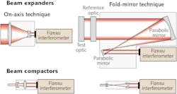
A practical alternative is to offer zoom through discrete expansion optics—that is, two or more sets of optical assemblies that can be exchanged to change the output beam diameter. These are commonly referred to as beam expanders that enlarge the collimated beam, or beam compactors that reduce the beam size from 100 mm to 50 or 33 mm, for example (see Fig. 2).While beam expanders and compactors for a variety of test conditions improve imaging performance and conserve light for low exposure times, they also add cost and require the accessories to be mounted/unmounted on the system as aperture sizes are varied. Still, they can be a viable zoom compromise for many dynamic applications since light is conserved and no changes in exposure time are required.
Continuous incoherent zoom
The earliest solutions to imaging test parts of various sizes were the use of continuous optical imaging zoom (“back end”) systems. An intermediate image is formed on a rotating ground glass that converts the imaging system to “incoherent imaging.” This allows the use of commercial off-the-shelf video zoom lenses. For stable temporal applications, or the use of on-axis dynamic systems, imaging-optics-based continuous zoom can be a good choice, because the image can be adjusted to fill the maximum number of detector pixels.
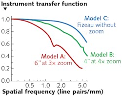
One drawback of continuous-optical-imaging zoom is that, as the image size increases, less light hits the camera, requiring longer integration times and increasing sensitivity to vibration and thermal effects. This type of imaging system performs poorly with off-axis dynamic configurations and does not support high-resolution cameras. But a more important drawback is that while convenient to manufacture, zooming imaging optics do not offer real resolution. Instead, resolution is limited by the incoherent image produced on the ground glass screen, and thus the imaging optics zoom is “empty,” meaning the image simply becomes both larger and blurrier at the same rate.
“Empty zoom has been a thorn in the side of optical manufacturers for decades and sort of a dirty secret,” says James Millerd, 4D Technology president. “An interferometer system that offers a continuous zoom—specifically with increased information in the enlargement—has been on their wish list for quite some time.”
Continuous coherent zoom
To some extent, all the foregoing zoom configurations discussed are compromises. The ideal scenario is continuous coherent optical zoom over a wide range of magnifications, enabling sampling maximization for any given measurement and high-quality data with maximum lateral resolution.
A solution superior to imaging optics zoom is to put a continuous zoom in the expansion optics, conserving both light and resolution. Coherent expansion optics zoom—with no ground glass intermediate stage—offers improved imaging and retrace performance, but is considerably more challenging to design than an incoherent system. It must control output wavefront, imaging quality, and stray reflections—all at the same time.
To fill the gap left by ADE Phase Shift after discontinuing its imaging optics coherent zoom capability when it was acquired in 2007, 4D Technology has a new offering. Its AccuFiz continuous optical zoom system has a built-in capability to readily measure the instrument transfer function (ITF) to ensure that the end-user can verify the performance of the system throughout its lifetime. With ITF calculation, users can readily assess measurement capability vs. spatial frequency (see Fig. 3).As most optical designers know, adding additional surfaces with power allows for improved correction capabilities for expansion-optics-based continuous-zoom Fizeau interferometers. AccuFiz uses five imaging elements as well as exotic glass types to enable high image quality, with both singlets and doublets of various powers combining to enable diffraction-limited imaging over a wide range of magnifications. Since these elements are in a coherent imaging space, this presents stringent requirements on cleanliness and coating quality, but the added complexity and expense are necessary to provide superior zoom operation.
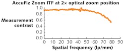
Even with these techniques, diffraction-limited imaging is not possible over the full 6X zoom range. Nevertheless, the system optics and zoom optics are carefully matched such that magnifications up to 2.5X give increased high-frequency data. At 2.5X zoom, the system can measure more than 72 lines/mm with 70% fidelity, compared to only about 29 lines/mm at the 1X zoom level (see Fig. 4).REFERENCE
1. See http://bit.ly/Fizeau.
Erik Novak, Ph.D., is director of business development and Edgar Schrock is marketing manager, both at 4D Technology, a Nanometrics business unit, Tucson, AZ; e-mail: [email protected]; www.nanometrics.com.


