Short coherence laser interferometer measures transparent domes
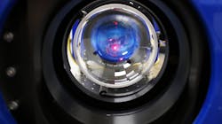
Thin, transparent domes enclose and protect imaging and guidance systems for applications in surveillance, aerospace, and defense applications. Since these components are always in the optical path, instrument designers and fabricators must establish proper tolerances and characterize the manufactured dome glass shape and thickness variations to maintain accurate imaging.
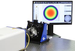
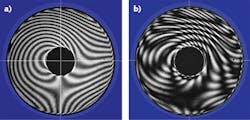
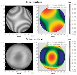
The large aperture of a Fizeau configuration laser interferometer typically makes it the instrument of choice for measuring such critical optical components. A Fizeau interferometer can image and test large areas of the convex dome surface in one measurement, with sufficient resolution to discern fine surface variations and imperfections (see Fig. 1).An interferometer measures surface height by comparing the shape of the test optic against a high-quality reference surface. The measurement beam is split in amplitude to produce two beams. One is directed to the test optic and the other reflects from the reference surface. When the beams recombine, they create a pattern of interference fringes (see Fig. 2a).
The shape of a fringe is directly related to height variations on the test part compared to the reference surface. While carefully shifting the position of the reference surface by small increments, several interference patterns are acquired from which the shape of the test surface can be determined with high precision.
Measuring challenges of thin transparent optics
Transparent domes, however, present several challenges for interferometric measurement. A typical Fizeau interferometer uses a long coherence laser source. With this standard source, any reflective surface that is parallel to the reference surface will generate interference fringes.
When measuring thin, parallel transparent optics (windows, domes, glass disks, etc.), interference occurs between all of the reflective surfaces, resulting in a complex interference pattern from which it is difficult or impossible to determine the shape of the test surface (see Fig. 2b).
Formerly, it was necessary to apply an antireflective coating to the back surface, thereby eliminating the extra interference fringes, to isolate and measure the individual surfaces of such an optic. Then, after measurement, the optic would be cleaned, the other side coated, and another measurement taken of the second surface. The process is time-consuming and can potentially be detrimental to the optic, especially when fragile coatings have been applied.
Short coherence source isolates the surfaces
In recent years, interferometers have been developed that combine a short coherence source with an adjustable path-match mechanism. The path-match mechanism can be tuned either manually or automatically to selectively interfere any combination of surfaces within the test path. Such a “surface isolation source” makes it possible to isolate and measure the front and back surfaces of transparent components as thin as 50 µm. Both measurements can be completed without repositioning the optic, which reduces measurement time and eliminates potential misalignment between the two measurements.
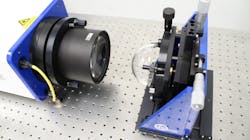
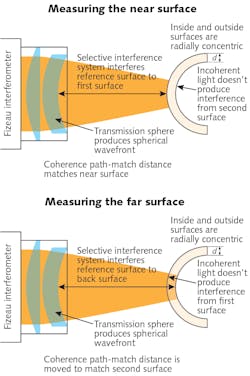
The surface isolation source can also be applied for measuring curved surfaces and is ideal to test radially concentric, transparent domes. In this case, rather than using a flat reference surface, a transmission sphere with approximately the same F/# (that is, curvature) as the dome is used as the reference.Figure 3 shows this measurement setup with a Fizeau interferometer. The transmission sphere can be seen on the front of the instrument. The test dome is mounted in a separate five-axis mount for accurate positioning.
The surface isolation source enables each surface to be isolated and measured sequentially, without re-fixturing the part. As shown in Figure 4, adjusting the path-match distance isolates either the outer or inner surfaces for measurement.From these two measurements, it is also possible to obtain accurate maps of both surfaces and the optical total thickness variation (OTTV) across the measurement area. The variation can be calculated by subtracting the inner surface measurement from the outer surface measurement. Scaling the OTTV result by the material index of refraction yields the physical thickness variation.
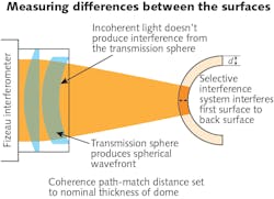
Alternatively, OTTV can be measured by setting the path-match distance such that interference occurs between the front and back dome surfaces, rather than with the reference surface. Such a “solid cavity” test (see Fig. 6) can be more reliable as it eliminates any degradation due to air turbulence or thermal currents.Measuring radius of curvature
A Fizeau interferometer can also be used to measure the radius of curvature of a dome. By measuring the dome first at the cat eye and then at the confocal position, the radius of curvature can be measured accurately. A high-precision stage is used to control and adjust the sample location relative to the interferometer for the two measurements.
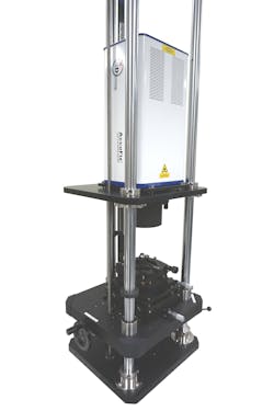
Figure 7 shows a Fizeau interferometer in a vertical, look-down configuration with a precision positioning stage.Dome measurement considerations
A critical assumption implicit in the use of a Fizeau interferometer is that the reference and test beams follow nominally identical paths through the instrument’s imaging optics. As a result, aberrations and thickness variations in the system’s internal optics cancel out, and therefore they do not add significant error to the measurement. If the test configuration is “off axis” and tilt is introduced between the test and reference beams, then any errors in the optical train will appear as errors in the measurement result as well.
When measuring a flat optic, the errors introduced are typically negligible and do not impact measurement accuracy. However, when measuring a strongly curved surface such as a non-spherical dome, the errors become significant and can distort the measurement data. An on-axis Fizeau interferometer is therefore the preferred instrument for measuring domes.
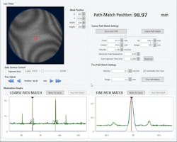
Measurement setup time is another important consideration. The path-matching operation can be automated; Figure 8 shows the result of such a scan. Note the two sharp modulation peaks at approximately 93 mm (interference between the outer dome surface and reference) and 99 mm (interference between the inner dome surface and reference). Once the software-controlled path-match scan is complete, an operator can select the surface of interest to test, fine-tune the scan at the appropriate peak, and acquire the measurement.Conclusion
Measuring the shape and thickness of transparent domes is a challenging application that can be accomplished with very few instruments. A short coherence source Fizeau interferometer is an ideal solution, providing the ability to selectively isolate the dome’s outer and inner surfaces. Both surface quality and total thickness variation can be measured for radially concentric, spherical domes. The same technology can be used to measure a variety of thin, transparent optical elements such as windows, glass disks, etc.
Mike Zecchino | Technical Communications, 4D Technology
Mike Zecchino is in technical communications at 4D Technology, Tucson, AZ.
Shawn McDermed | Applications Development Manager, 4D Technology
Shawn McDermed is Applications Development Manager at 4D Technology, Tucson, AZ.
