LONG-WAVE PHOTONICS: Millimeter-wave imager sees land mines

Land mines remain a deadly problem for countries around the world recovering from past wars; more than 100 million active land mines in Afghanistan, Cambodia, Angola, and other countries lay ready to kill or maim. Despite the opacity of soil, experimental photonic approaches to detecting buried land mines exist, such as the use of lidar to track mine-sniffing bees (see www.laserfocusworld.com/articles/238629) and microwave heating followed by IR detection (see www.laserfocusworld.com/articles/88424). Now, researchers at the University of Central Florida (UCF; Orlando, FL) are directly imaging land mines in soil with millimeter waves using optical techniques.1
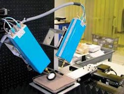
The technique is aimed at sensing antipersonnel mines, which typically lay at depths of a few centimeters, as opposed to antitank mines, which are buried as deep as 40 cm. Using soil samples from around the world, the UCF researchers set up a laboratory experiment based on the use of 90 to 140 GHz radiation, high-density polyethylene lenses, and so-called vector-network-analyzer (VNA) modules for creating and detecting the radiation (a VNA is an electronic device that, when used as a receiver, can detect amplitude and phase of the signal).
A chosen soil sample layered over a land mine was placed on a two-axis translation stage and the sample raster-scanned to obtain a 29-line image, measured from 90 to 140 GHz in 1 GHz steps. Land-mine types measured included a TS-50, which has a metal pressure plate within it and 50 g of T4 explosive; and an M14, which has very little metal and 29 g of tetryl explosive. The researchers also imaged various sorts of minefield debris such as shell casings and fuse lighters.
Principal-component analysis
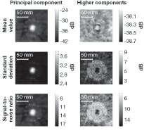
For dry soil obtained locally (central Florida) and mines buried 15 mm deep, images were scanned in 2 mm steps. Because the images taken at individual frequencies each contained only small amounts of information, the researchers used principal-component analysis to combine the 51 different scans of each land mine into one image with a high signal-to-noise ratio. (Principal components are variables selected such that there is no correlation between them; linear combinations of them can be combined to recreate the original image).For each rectified image, three different analyses were done on the principal component and the higher components (see figure), which found the mean, the standard deviation, and their signal-to-noise ratio). The sets of image data provide different ways to best see land mines of differing compositions. The structure of a TS-50 land mine, for example, is best visualized through its higher components, while the identifying structure of the top cap of an M14 mine is best seen in principal-component images.
“We have currently done measurements to 50 mm,” says Todd W. Du Bosq, one of the researchers. “We have measured the transmission of many types of soils found throughout the world, but have not done any imaging measurements with them at the moment.”
Certain soil properties can make it harder to see land mines with millimeter waves. “Soil particles range from 2 mm (coarse sand) to less than 0.002 mm (clay),” says du Bosq. “However, other particles may be present in the soil, including rocks and vegetation that will increase scattering. Moisture present in the soil will decrease the penetration depth due to absorption.” While the experiments were primarily done on mines placed under a flat soil surface, the researchers were also able to identify mines under disturbed soil.
“We have measured the transmission of 19 different soil samples found throughout the world from 90 GHz to 4.2 THz,” adds du Bosq. “We are planning to initiate field trials at the mine lanes at U.S. Army Night Vision Labs (Fort Belvoir, VA).”
REFERENCE
1. T.W. Du Bosq et al., Applied Optics 45(22) (Aug. 1, 2006).

John Wallace | Senior Technical Editor (1998-2022)
John Wallace was with Laser Focus World for nearly 25 years, retiring in late June 2022. He obtained a bachelor's degree in mechanical engineering and physics at Rutgers University and a master's in optical engineering at the University of Rochester. Before becoming an editor, John worked as an engineer at RCA, Exxon, Eastman Kodak, and GCA Corporation.
