Optical design is key to machine-vision systems
Careful consideration of an object to be analyzed helps determine appropriate system design.
Jonathan S. Kane
Machine-vision systems have tremendous appeal because they eliminate repetitive measurements while increasing manufacturing yields and response times. Although the research community has been concentrating on optical parallel processing, a basic machine-vision inspection system still contains a lens, a camera, and an image-processing card, together with a processor and an algorithm (see "Optical processor will increase system efficiency," p. 142). Because the optics often are a limiting factor in sophisticated machine-vision systems, knowledge and use of the laws of optical physics enables a system designer to maximize system performance. As a general rule, a lens should be used for the magnification for which it was designed.
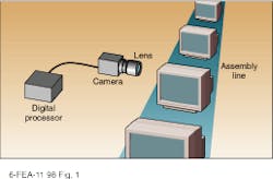
Machine vision is a term encompassing semiconductor inspection to automatic guidance systems. For this article, machine vision means the act of acquiring an image by a lens/camera combination and then digitally processing that image to locate and act upon a salient feature (see Fig. 1). Furthermore, the discussion is restricted to inspection tasks based upon pattern recognition in which an end user needs to quickly and automatically locate a flaw in a product line.
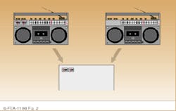
The basic procedure involves illuminating the object and using a lens system to produce an image on a camera, which is then communicated to an image processor. The processor can be programmed to perform any number of image operations; a common one is matching a template. A template is compared to the image point by point, and any significant differences triggers an alarm and the piece is rejected (see Fig. 2).
Front-end requirements
The optical front end of such inspection systems is crucial. At Computer Optics Inc. (Hudson, NH), analysis begins with the features of the object under question, so that the highest-quality image is sent back to the camera plane. This important area is frequently ignored by designs that concentrate on the electronics and software. For example, recently a client appointed a relatively junior worker the task of setting up a vision system for in-house inspection stations. The engineer bought the processor board, illumination system, camera, and lens from different sources and then spent weeks programming the processing board and, eventually, demonstrating a prototype that basically worked.
The prototype, however, had the common problem that fine detail could not be adequately resolved. In this case, the lens/camera combination was inappropriate for the required resolution. No amount of digital processing could help because the lens was not appropriate for the job. The lens to provide the proper magnification at the finite distance was identified by consulting the Computer Optics lens library.
In addition, sometimes the image may appear too dark, be the wrong size, or go in and out of focus as items pass under the inspection system. This last problem is quite common, and the solution is to stop down the lens (increase the f-number) so that the depth of field is increased. Of course, the improvement comes at the cost of light intensity. Each f-number represents reducing the light throughput by half, so the result is that the camera plane receives an image that is too dark. Too often a designer will attempt to solve this problem by purchasing a high-power lighting system to saturate the inspected piece with light. An alternative approach is to attempt to digitize the image and use histogram equalization. However, lower light levels tend to be overemphasized, which decreases the signal-to-noise level of the normalized image.
Another example of a problem with machine-vision-system design involves a system integrator that produced a high-resolution inspection station. The digital algorithms produced an unacceptably high bit-error rate (signal-to-noise ratio too low). The company had increased the light level, but could not locate a sufficiently powerful light source with the necessary physical dimensions. To obtain the necessary lens performance, the lens had been stopped down to f/22 (nearly closed). The solution was to design and manufacture a lens system that could be operated at full aperture, eliminating the need for an illumination system and allowing the system to be operated with only room light. The overall cost of the system dropped, and performance improved.
Early design analysis
The most important aspect of system design is that the features that must be acquired to reach an automated decision should be identified up front. In many cases, an off-the-shelf lens suffices. For a client using a dye that turns red when an abnormal cell reacts with it, for example, a standard-resolution lens is more than adequate because the machine-vision system only needs to determine if red is in the picture or not.
By asking some important questions, optical engineers can get a feeling for the necessary performance requirements of a given lens/camera system (see "System design considerations").
There has been general movement toward smaller camera size such as 1/2-in.- or even 1/3-in.-diagonal chip size. Although this may be acceptable for some applications, the space-bandwidth product generally is smaller, which makes the constraints outlined above more limiting. In other words, if all else is equal, 2/3-in. camera size provides a larger field of view because there are more total pixels. A similar trade-off occurs when comparing light-gathering ability to depth of focus. Generally speaking, the greater the depth of focus, the lower the light-gathering ability.
These trade-offs make up the heart of what is physically possible with a lens system, regardless of what lens is actually used. Once these trade-offs are addressed, the system integrator can go to the marketplace to order a lens/camera combination that is not overspecified (expensive) but that still meets the minimum acceptable requirements. o
FIGURE 1. Basic components of a machine-vision system include lens, camera, and imaging circuit card. A digital processing system and algorithm are essential for processing the image and translating it into a usable format.
FIGURE 2. Many machine-vision systems use a template-matching paradigm in which an existing template (left) is compared to an acquired image (right). Nonmatching parts are highlighted in conjunction with an alarm from the control system to alert the operator.
Optical processor will increase system efficiency
Serial processing is fundamentally limited because the processor must perform one task at a time. For this reason, parallel processors are currently a focus of research and development--they hold the promise of extremely rapid processing. Optical processors, in particular, are being examined because, if the incoming image signal could be processed at the detector plane, it would avoid the serial bottleneck entirely.
Optical processors based on the theory originally developed by Dennis Gabor use Fourier processing to perform pattern recognition.1 It can be shown mathematically that the Fourier transform of a given object one focal distance in front of the lens appears one focal length behind the lens. The Fourier transform works regardless of where the object is in the frame. By performing matching in the Fourier plane, a target can be pulled out of a scene.
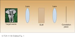
The basic workhorse of the optical signal processor is a correlator consisting of an image-gathering device, a Fourier-transform lens, a spatial light modulator (SLM), another lens, and the output sensor (see Fig. 1). The SLM is any device capable of modulating information onto an optical beam. Because the processing speed is limited by the ability of the SLM in use, much research has been focused on development of faster and more useful such modulators.
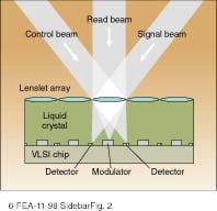
A liquid-crystal SLM developed at the US Air Force Research Laboratory (Han scom AFB; Bedford, MA) in conjunction with Displaytech (Longmont, CO) has both input and output pads collocated on the surface such that data can be read in, processed, and read out all from the same device without requiring the aid of an external computer (see Fig. 2).2 Similar devices are now under commercial development at companies such as Displaytech and CoreTek (Burlington, MA). Displaytech has concentrated on making a compact ruggedized correlator; CoreTek has been developing an ultrahigh-speed device.
J. S. K.
REFERENCES
1. D. Gabor, Nature 161, 777 (1948).
2. J. S. Kane, T. G. Kincaid, and P. Hemmer, SPIE Optical Engineering 37(3), 942 (1998).
FIGURE 1. Parallel image processing is possible with an optical processor, which contains an optical correlator that recognizes patterns in a scene by performing a Fourier transform. The incoming signal is processed at the detector plane, thus greatly speeding the task.
FIGURE 2. Multiple input-output spatial light modulator, such as one coinvented at the US Air Force Research Laboratory, has input and output pads collocated, allowing data to be read in, processed, and read out from one device without external processing.
System design considerations
Some of the important questions that should be addressed in designing any machine-vision system include
n What is the distance to the object plane from the camera focal plane? Generally this information can be used to specify the focal length of the lens.
n What is the required minimum feature size (resolution) in the object plane? This can be complex, especially when using coherent lighting, because diffractive effects come into play. One rule of thumb is to ensure that the acquisition system has at least a factor of two better resolution then the minimum feature size.
n What detector is used in the focal plane? Specifically, if using a pixelated device, how many pixels are available? If this is a parameter that can be left open, generally speaking, the more pixels the better. A cost/performance trade-off will have to be performed.
n What is the field of view? How large is the overall image? Does the entire image need to be captured at one time? Can it be scanned? Is the object moving?
n What depth of focus is necessary? Is the object moving in regard to the lens/sensor combination? If so, how much?
n What are the lighting requirements? Is a minimum amount of throughput necessary for the system to function? Is space available for illumination sources? What is the nature of the material to be viewed ? Is it specular or reflective?
n Is zoom capability required? Would digital zooming suffice or is pixelation a problem?
n Are there any size or weight restrictions? Is there a restriction on length or outer diameter? What is the overall environment? What is going on outside the lens? Is the lens moving? What is being produced on the factory floor?
n Can distortion be tolerated and taken out later with the digital system? Can defocus be tolerated? If true object size is needed regardless of focus of the image, then a telecentric lens is preferable.
n What is the estimated market price for the system? Using an expensive lens/camera combination may solve the imaging problems only to produce a wonderful system that cannot be sold.
J. S. K.


