Remote optical amplification extends transmission spans
Unrepeatered systems employing remote amplification may become less-expensive alternatives than repeatered
systems for distances up to about 425 km.
Per Hansen
Optical in-line amplifiers optically powered via the transmission fiber present a promising technology for increasing the distance between electrically powered equipment in optical transmission systems.1, 2 Repeaters are an effective means of increasing the span length but require electrical powering and associated performance monitoring, which adds significantly to installation and maintenance costs.
Unrepeatered systems based on remote amplification, however, may become less-expensive alternatives to repeatered systems for distances up to approximately 425 km.3 Remotely pumped amplifiers are particularly attractive for submarine systems, in which repeaters pose special challenges and add significantly to the cost. Optical power levels in the range of 100 mW and above are available from semiconductor-based pump sources, making remote pumping a realistic option. The first generation of commercial systems based on remote pumping with 100-mW semiconductor lasers is already a reality (see OCommercial systems go the distance,O p. 81). Emerging technologies promising powers of up to several watts in the desired wavelength range from 1450 to 1490 nm will make such system topologies even more attractive.4
Amplifier types
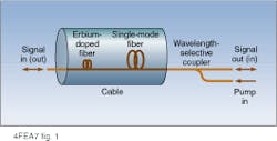
A remote amplifier basically consists of an amplifying medium, the connecting transmission fiber through which the pump is delivered, and a pump source (see Fig. 1). Fiber-based amplifiers, which inherently rely on optical pumping, are of most interest for remote applications?Raman and erbium-doped fiber amplifiers in particular because they represent relatively mature technologies (see photo).
The amplifying medium is often a segment of erbium-doped fiber designed to obtain properties such as good noise performance and high conversion efficiency. The conversion efficiency from optical pump power to optical signal power is critical because available pump power at the remote location is limited by how much power can be injected into the fiber and by the loss incurred during propagation in the fiber span that separates the pump source and the amplifier.
High optical powers in a fiber give rise to Raman scattering, which results in power being transferred from the pump to a signal at a higher wavelength. Because Raman gain exhibits an exponential dependence on the pump power, the gain is distributed over a distance of several tens of kilometers with the peak gain occurring at the terminal. A combination of a remotely pumped erbium-doped fiber amplifier and Raman gain in the transmission fiber through which the pump is delivered is often the most attractive implementation.
Possible variations to the basic topology shown in Figure 1 include dedicated pump fibers and pump reflectors. Adding more fibers beyond the transmission fiber offers a means for connecting more than one pump source and thereby increasing the maximum pump power that can be delivered to a remote location.
The maximum pump power that can be launched into a shared pump-signal fiber is typically limited by double Rayleigh scattering of signal and amplified spontaneous emission because of the accompanying Raman gain, which increases exponentially with the pump power. The increase in spontaneous emission noise rapidly decreases the signal-to-noise ratio at high Raman gain levels. Without a signal present in the fiber, the maximum pump power that can be launched is therefore somewhat higher. Furthermore, a dedicated pump fiber offers an extra degree of freedom in terms of choosing the pump wavelengths as well as the optimum erbium-doped fiber gain and Raman gain levels in a system application.
Pump reflectors, which reflect the remnant pump power not absorbed during the first pass through the remote erbium-doped fiber amplifier, considerably increase the efficiency. Experiments have shown typical signal gain improvements of
2 dB. Pump reflectors can be fabricated as fiber Bragg gratings with insignificant insertion loss at the signal wavelength and more than 97% reflection over the pump wavelength band.
Remote postamplifiers
In a single-span transmission system, remotely pumped optical amplifiers can be implemented at transmitter or receiver terminals. However, the power budget improvements are vastly different because of the difference in signal levels at the two locations.5
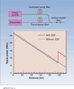
The signal power that can be launched into a fiber span without excessive penalties is limited by the fiber nonlinearities. A remote postamplifier offers an increase in the power budget without incurring additional penalties. Figure 2 depicts a typical schematic of a transmitter that incorporates a remotely pumped erbium-doped fiber segment pumped via a dedicated pump fiber. Typical realized improvements are in the range of 3 to 6 dB for maximum launched signal and pump powers of about 27 dBm and about 31 dBm, respectively.
The optimum location of the erbium-doped fiber segment for a given pump power is governed by a trade-off between the power limit set by fiber nonlinearities and the power conversion efficiency, which declines with reducing signal and pump powers. Penalties from fiber nonlinearities are incurred during the first tens of kilometers where the signal power is very high. The location and output power of the remote postamplifier should therefore be chosen so that no further degradation from nonlinearities is suffered due to the increase in signal power provided by the amplifier.
Copropagation of the pump and the signal in the transmission fiber induces Raman gain for the signal very close to the transmitter where the signal power is already limited by the fiber nonlinearities. Consequently, a dedicated pump fiber is preferable for remote postamplifier applications. Furthermore, when high pump powers travel in the same direction as the signal in the same fiber, intensity noise is transferred from the pump to the signal because of the femtosecond response time of the Raman scattering process.
Remote erbium-doped fiber preamplifiers
An erbium-doped fiber segment pumped from the receiver terminal offers the largest power budget improvement and is attractive even with modest pump power levels. An improvement of as much as 10 dB can, for example, be obtained with only
100 mW of pump power.
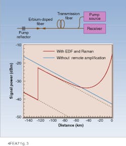
Figure 3 illustrates a remotely located erbium-doped fiber segment pumped from the receiver terminal via the transmission fiber. In this example, the remote erbium-doped fiber amplifier provides 18 dB of gain at a distance of 123 km from the receiver. Over the last
60 km before the receiver, the Raman gain from a pump power of 31 dBm amounts to about 28 dB, and the optical power incident on the receiver at the terminal is approximately -15 dBm. The received power is, however, insufficient to ensure that the circuit noise of the PIN detector and associated electrical amplifier stages will be negligible compared to the noise originating from the amplified spontaneous emission.
Consequently, a local optical preamplifier preceding the PIN detector is required to achieve optimum performance. In Figure 3, this local preamplifier is part of the receiver, and overall improvement in system power budget is 19.7 dB.
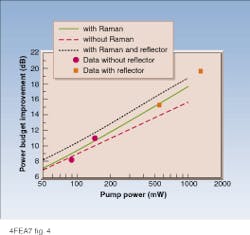
Figure 4 shows measured and calculated power-budget improvements versus launched pump power for a
2.5-Gbit/s data rate. Contribution to the power-budget improvement from Raman gain increases with increasing pump power, whereas the pump reflector provides a 1-dB improvement independently of the pump power.
Distributed Raman preamplifiers
Raman preamplification in the transmission fiber can also be used without an erbium-doped fiber segment. The implementation requires only a wavelength-selective coupler and a pump source and is therefore relatively simple and inexpensive. As no modifications of the cable are required, this is an attractive method for upgrading already-installed systems.
The improvement in power budget from Raman preamplification is limited by double Rayleigh scattering in the fiber that causes the amplified spontaneous emission noise from the Raman process to increase rapidly at high gain levels. The pump power required to realize the optimum performance depends on fiber characteristics such as the Rayleigh scattering coefficient, the Raman efficiency, and the background loss of the fiber at the signal and pump wavelengths.
System experiments at data rates of 10 Gbit/s have shown improvements of up to 7.4 dB in pure silica-core fiber with
1.2 W of pump power at a wavelength of 1450 nm.6 Optimum performance is reached at a much smaller pump power of approximately 600 mW in a typical dispersion-shifted fiber, mainly due to the higher Raman efficiency.
Overall, remote amplification is an attractive method for increasing the distance between electrically powered equipment in optical transmission systems. Remotely pumped preamplifiers deliver the largest improvements in performance relative to the required pump power and have therefore been implemented in commercial systems since 1995. Because of their excellent reliability properties conventional semiconductor lasers have been the preferred pump source in spite of maximum fiber-coupled output powers below 200 mW per diode. However, a new generation of pump sources based on multiplexed high-power lasers or broad-area lasers is being developed and has the potential for making remote pumping even more attractive. o
REFERENCES
1. P. B. Hansen et al., IEE Electron. Lett. 31(17), 1460 (1995).
2. S. Sian et al., Digest Optical Fiber Communication Conference, paper PD-26 (San Diego, CA, 1995).
3. C. F. Pedersen, Digest SubOptic, paper THP2-A (San Francisco, CA, 1997).
4. S. G. Grubb et al., Digest Topical Meeting on Optical Amplifiers and Their Applications, paper SaA4 (Davos, Switzerland, 1995).
5. P. B. Hansen and L. E. Eskildsen, Optical Fiber Technology 3(3), 221 (1997).
6. P. B. Hansen et al., Photon Technol. Lett. 9(2), 262 (1997).
FIGURE 1. In generic remotely pumped amplifier topology, the amplifying medium is often a segment of erbium-doped fiber.
FIGURE 2. Postamplification with an erbium-doped fiber can typically boost the transmitted signal in the range of 3 to 6 dB for maximum launched signal and pump powers of about 24 dBm and 30 dBm, respectively. The graph illustrates the power evolutions in the depicted system topology (red line) as well as in the comparable system without remote amplification (blue line).
FIGURE 4. Curves show measured and calculated power budget improvement from implementing a remotely pumped erbium-doped fiber segment. Dashed line shows results for erbium-doped fiber amplification only, which corresponds to the topology incorporating a dedicated pump fiber. Solid and dotted lines are power-budget improvements including Raman gain?for pumping via the transmission fiber?without and with a pump reflector.
Commercial systems go the distance
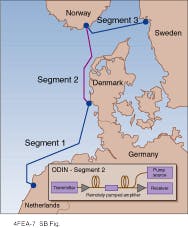
At least four optical transmission systems in commercial service use remote amplification. Segment 2 of the STM-16 (2.488 Gbit/s) ODIN system, which was installed by DSC (Ballerup, Denmark) in 1995, incorporates an erbium-doped fiber section remotely pumped from the receiver terminal via the transmission fiber (see figure).1 Segment 2, which spans 296 km over pure silica-core fiber, exhibits a total power budget available for fiber loss and margin of 67 dB. The signal launch power at the transmitter is 18 dBm. Approximately 100 mW of pump with a center wavelength near 1480 nm is launched from the receiver terminal into the 55-km-long fiber span that separates the remote erbium-doped fiber segment from the terminal.
The Cayman-Jamaica fiber system, which was delivered by Alcatel Submarine Systems (Paris, France), incorporates remotely pumped preamplifiers in segments connecting Montego Bay and Kingston on Jamaica.2 Forward-error-correction equipment in this system translates the 2.488-Gbit/s data rate into a 2.666 Gbit/s line rate. The total length of the span, which consists of pure silica-core fiber, is 350 km. A remote, erbium-doped fiber amplifier is pumped via the 63-km-long transmission fiber span separating it from the receiver terminal.
The unrepeatered system, RIOJA - Segment III, which was built and delivered by STC Submarine Systems (London, England) in 1995, connects Belgium and the Netherlands with
a capacity of 2.488 Gbit/s.3 The
283-km-long system employs standard non-dispersion-shifted fiber. Two 45-km-long dedicated pump fibers deliver pump power from two semiconductor laser diodes at the receiver terminal to the remotely located erbium-doped fiber segment.
Remotely pumped amplifiers are also incorporated into the Fiberoptic Link Around the Globe (FLAG) cable system, which comprises a total of 27000 km of cable.4 FLAG was delivered for service in 1997 by Tyco Submarine Systems (Morristown, NJ) and KDD (Tokyo, Japan). The 233-km-long terrestrial segment between Alexandria and Cairo in Egypt employs remote pumping as well as forward-error-correction coding for transmitting 5 Gbit/s of data per fiber.
P. H.
REFERENCES
1. C. F. Pedersen, Digest SubOptic, paper THP2-A (San Francisco, CA, 1997).
2. E. Brandon, A. Gladston, and J-P Blondel, Digest Optical Fiber Communication Conference, paper TuL1 (Dallas, TX, 1997).
3. S. J. Pegrum and S. S. Sian, Digest Conf. on European Fibre Optic Communications and Networks, 123 (Brighton, UK, 1995).
4. T. Welsh et al., IEEE Communications 34(2), 30 (1996).
Segment 2 of ODIN transmission system
incorporates remote amplification.
