LiSGaF offers performance edge over LiSAF
LiSGaF offers performance edge over LiSAF
In direct comparisons, low-loss Cr:LiSGaF generates higher power than low-loss Cr:LiSAF, while remaining thermally more robust for simplified cooling and reduced
susceptibility to damage.
Arlete Cassanho and Hans Jenssen
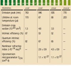
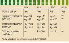
The development of the chromium-doped colquiriite laser crystals lithium calcium aluminum fluoride (LiCAF), lithium strontium aluminum fluoride (LiSAF), lithium strontium gallium fluoride (LiSGaF), and lithium calcium gallium fluoride (LiCaGaF) began with LiCAF, a naturally occurring mineral originally discovered in a Bolivian tin mine.1 While these materials display similar spectroscopic properties, they have their own growth idiosyncrasies (see table on p. 170). For example, LiCAF is more robust than LiSAF and LiSGaF and features more advantageous thermo-optical properties (see table, right). Crystals of the material currently suffer from excessive scattering, however, which causes loss and makes LiCAF a less attractive candidate for laser systems.
The interest in developing compact, all-solid-state femtosecond lasers has fueled much of the development of Cr:LiSAF and concomitantly Cr:LiSGaF. LiSAF has been grown commercially since 1992 (at Lightning Optical, now VLOC, Tarpon Springs, FL) with much lower losses than LiCAF. Because of this availability, most of the laser development to date has been done using LiSAF.
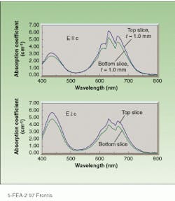
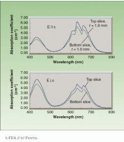
In 1992, chromium-doped LiSGaF (Cr:LiSGaF) was grown with low scatter losses at Lawrence Livermore National Laboratory (Livermore, CA), but only in very small sizes because of the limited availability of high-quality gallium fluoride (GaF3).2 Both Cr:LiSAF and Cr:LiSGaF feature a strong absorption band ranging from 600 to 700 nm, permitting efficient diode-pumping at 670 nm by indium gallium phosphide diode lasers (see figure, right). The effective emission cross section of Cr:LiSGaF is approximately 70% of Cr:LiSAF. The emission peak is shifted slightly toward shorter wavelengths, its fluorescence lifetime is longer (see table, right). Although the two materials have similar tuning ranges, LiSGaF displays better thermo-optical properties than LiSAF, potentially making it more attractive than LiSAF for higher-power applications.
In 1992, at the Massachusetts Institute of Technology (MIT; Cambridge, MA) we developed a synthesis technique for Cr:LiSGaF. Using the method, we grew a 4-in.-long crystal with passive scatter loss per centimeter approaching 0%.3 In 1995, Yanovsky, Wise, and collaborators at Cornell University (Ithaca, NY) obtained tunable 80-fs pulses from a diode-pumped, Kerr-lens-modelocked Cr:LiSGaF laser using a crystal from MIT.4
LiSAF vs. LiSGaF
It is difficult to ascertain the advantages of one crystal compared to another when comparing results of systems built by different groups. Direct-comparison experiments between low-loss Cr:LiSAF and Cr:LiSGaF have been conducted mainly by Sorokina5 in Austria and Yanovsky and Wise6 at Cornell University. Balembois and collaborators at Institut DíOptique (Orsay, France) compared the performance of low-loss, 3-mol%-doped Cr:LiSAF and Cr:LiSGaF in continuous-wave, diode-pumped, Q-switched operation.7 The grou¥obtained four times more power from the LiSGaF system than the LiSAF system, confirming previous observations that LiSGaF is preferable over LiSAF for higher-power applications.
Based on these reported laser results, the apparent superior performance of LiSGaF as compared to LiSAF should be explained by a comparison of the properties of the two materials. These characteristic properties are very similar, however, so the measurement process must be performed with high accuracy. Reported parameters vary considerably from research grou¥to research group; to date only a few controlled experiments directly comparing LiSAF and LiSGaF have been performed.
The US Department of Energy recently funded VLOC to make a comparison of LiSAF and LiSGaF. The few published reports comparing the two contrasted low-loss LiSGaF with higher-loss LiSAF. To evaluate the materials on an even basis, we synthesized LiSAF using a procedure based on the techniques developed for LiSGaF. Crystals of both materials have been grown with passive scatter losses of less than 0.1%/cm, such that a reliable comparison between the two materials can now be made. As an added dividend, LiSAF crystals with even lower scatter losses are now commercially available. Even crystals doped with u¥to 6 mol% chromium have achieved losses as low as 0.05%/cm for 20-cm-long slabs.
With the reduction of the scatter losses in LiSAF, one difference between the materials has been eliminated. Physical properties now become an important factor in determining which crystal is better for specific applications. The thermal expansion of LiSGaF is both lower and more isotropic than that of LiSAF. In addition, the thermal conductivity has been found to be slightly higher than that for LiSAF. These characteristics make LiSGaF a more robust, high-performance laser material. They also translate into an advantage in the growth process, reducing the risk of cracking during cooling.
Prior to 1993, the high scatter observed in Cr:LiSAF, which increased with the chromium doping level, was caused by poor-quality chromium fluoride (CrF3). Although the purity of CrF3 can be improved by standard fluorination techniques, the synthesis of pure GaF3 is not so simple. Crystals grown with inferior GaF3 result in a small section of clear material with the remaining boule consisting mostly of bubbles.
If starting ma terials of good quality are available for both LiSAF and LiSGaF, the growth by the Czochralski technique--pulling the crystal from a melt--is very similar. Typically pulling u¥to 50% of the melt for LiSAF yields low-loss material, while u¥to 70% of the melt can be pulled for LiSGaF. We have noticed less evaporation for LiSGaF during the process, as well as less cracking. However, for the same thermal gradients, LiSGaF exhibits higher probability of multigrain growth than LiSAF, making temperature stability during the growth period a far more critical issue for LiSGaF. In addition, LiSGaF is more sensitive to oxygen or moisture contamination in the furnace.
One parameter of interest during the growth of doped crystals is the distribution coefficient k of the dopant in the host. The dopant concentration along the length of a boule is given by
C = C0 k(1-g)k-1
where C0 is the dopant concentration in the melt and g is the crystallized fraction of the initial melt volume. The closer k is to unity, the more uniform the dopant concentration along the length of the crystal will be.
We determined the chro mi um distribution coefficient for LiSGaF and LiSAF by comparing the optical absorption of chromium for slices taken from the to¥and bottom of each boule, then applying the equation for k in terms of absorption coefficient a
a = a0k(1-g) k-1
and found that k is 1.3 for LiSGaF.
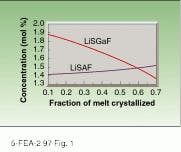
Early reports on the growth of Cr:LiSAF reported the concentration of chromium along the crystal as very uniform. Not all of the chromium added to the melt was incorporated in the crystal, however, and this percentage depended on the quality of the CrF3 used. With fully processed starting material, we found the chromium distribution coefficient in LiSAF to be equal to 0.94. LiSAF displays more dopant uniformity along the length of the boule than LiSGaF (see Fig. 1).
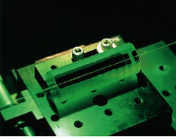
In 1993, Cr:LiSAF crystals exhibiting scatter loss less than 0.5 %/cm were routinely available, with some crystals dropping as low as 0.1%/cm (see Laser Focus World, September 1993, p. 85). The ultimate quality was, however, still dependent on commercial sources of good fluoride starting materials. The defects responsible for scatter losses in LiSAF can be detected by the trace of a laser beam crossing the boule longitudinally or by transverse white-light illumination (see Fig. 2).
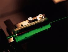
Previous reports on LiSAF9 proposed that these defects could only be eliminated with postgrowth annealing similar to the heat treatment proposed for LiCAF.10 If sufficiently pure starting materials are used, however, annealing is not necessary. Defect-free crystals have been grown with 0.8% chromium doping, for example (see Fig. 3). Similarly, with high-quality GaF3, Cr:LiSGaF crystals can be grown with losses less than 0.1%/cm. When a green helium-neon laser beam passes through the crystal, it generates weak red fluorescence that can only be seen when the boule has very low scatter losses.
Other issues such as wavefront quality that affect laser operation in large-diameter rods are still a problem, and work is in progress in this area at VLOC. In this respect, LiSAF and LiSGaF are similar, and advancements for one crystal will result in advancement for the other. The VLOC project to characterize and compare the two materials is still underway--as it continues, more accurate values of the optical and physical parameters for LiSAF and LiSGaF will become available. o
Acknowledgments
Part of this work was supported by the US Department of Energy (DoE) under SBIR contract DE-FG02-95ER82010 and by NASA Langley Research Center under SBIR contract NASA-20420. This support does not constitute an endorsement by the DoE or NASA of the views expressed in this paper.
References
1. S. A. Payne et al., IEEE J. Quantum Electron. 24, 2243 (1988).
2. M. Smith et al., IEEE J. Quantum Electron. 28, 2612 (1992).
3. A. Cassanho et al., OSA Proc. Advanced Solid State Lasers, 13, 2 (1992).
4. V. P. Yanovsky et al., Opt. Lett. 20, 1304 (1995).
5. I. T. Sorokina et al., Technical Digest Advanced Solid State Lasers Topical Meeting (1997).
6. V. P. Yanovsky et al., to be published in Journal of Selected Topics on Quantum Electronics.
7. F. Balembois et al., Opt. Lett. 22, 387 (1997).
8. A. Cassanho et al., Conference proceedings LEOS `96 vol 1, 96 (1996).
9. B. H. T. Chai et al., Proc. SPIE 1863 (1993).
10. J. J. De Yoreo, L. J. Atherton, and D. H. Roberts, J. Cryst. Growth 113, 691 (1991).
Cr:LiSGaF absorption curves measured with parallel (top) and perpendicular (bottom) electric fields show peaks in the 620- to 670-nm wavelength region. Variation between to¥and bottom 1-mm-thick slices is caused by the decreasing concentration of chromium as the percent of the melt crystallized increases (see Fig. 1).
FIGURE 1. Theoretical distribution of chromium in LiSGaF and LiSAF crystals along the boule for an initial melt concentration equal to 1.5 mol% shows greater variation along the length of the LiSGaF boule than the LiSAF boule.
FIGURE 2. Defects in Cr:LiSAF (loss less than 0.5%/cm) scatter the beam of a green helium-neon laser shining through the length of the boule. LiSAF was grown prior to 1993.
FIGURE 3. Proper synthesis technique and high-quality chromium fluoride dopant produces low-loss, 0.8% doped Cr:LiSAF crystal (top). Weak red fluorescence generated by a green helium-neon laser beam passing through 2.5% doped Cr:LiSGaF can only be detected by eye in the absence of scatter (bottom).
