FIBER FABRICATION: Single-mode fiber has very low bending loss

One can imagine the twists and turns taken by an optical fiber as it is routed in a fiber-to-the-home application. To lessen the problems that arise from kinks, researchers are developing fibers that, when bent in a small radius, don’t break and don’t lose much in light transmission (these are two mostly separate research efforts). Now, scientists at the Gwangju Institute of Science and Technology (GIST; Gwangju, South Korea) have created a single-mode fiber that has a bending loss of only 0.014 dB/loop at 1550 nm for a bending radius of 5 mm.1
Two approaches can be used to reduce bending loss in a fiber: adding a low-refractive-index “trench” within the cladding, and optimizing the mode-field diameter (MFD); the GIST group has used both. Prior to fabrication, the design required extensive optimization to keep other parameters such as the absolute dispersion and the dispersion slope within preset limits.
The maximum core index of the design was 1.456 (at 1550 nm), while the dip in index for the trench was 0.002. The researchers chose fluorine doping for the trench because the alternative doping element, boron, would diffuse too far into the surrounding regions. The core radius was 3.05 µm, while the MFD at 1550 nm was 7.7 µm.
The Gwangju researchers had to take into account the idiosyncrasies of the modified-chemical-vapor-deposition (MCVD) technique commonly used to fabricate fiber preforms, and used to create the preform for the experimental fiber. Normally, a fiber fabricated via MCVD shows a pronounced dip in refractive index at the center of its core; as a precaution, the researchers chose the worst-case scenario, in which the central dip in the core’s index reaches all the way down to the cladding index value, and used that in their design.
Tolerant of fabrication error
A preform with a germanosilicate glass composition for the experimental fiber was fabricated using MCVD; the fiber was drawn from the preform at a temperature of 2000°C to a diameter of 125 µm. And indeed, a measurement of the fiber’s refractive-index profile showed that the central dip in the core’s index had a value only slightly higher than that of the cladding. The fiber had a cutoff wavelength of about 1350 µm.
To measure the bending loss at different wavelengths, the researchers spliced two 1 m lengths of standard single-mode fiber (SMF) to a 2 m length of the experimental fiber. The input was a 1300 to 1650 nm spectral band from an amplified-spontaneous-emission source; the output was directed into an optical spectrum analyzer. In addition to the low results at 1550 nm, the fiber showed a 0.044 dB/loop bending loss at 1625 nm and 5 mm radius.
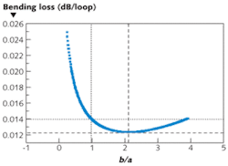
The fiber design also proved to be tolerant of imperfections in fabrication. For example, the design showed that b/a, where b is the distance from the outside of the core to the inner trench wall and a is the radius of the core, should ideally be 2.12; at this value, the bending loss would theoretically be 0.0123 dB/loop at 1550 nm. However, when the fiber was fabricated, b/a was actually only 0.98. Even so, the actual bending loss reached only 0.014 dB/loop (see figure).
The researchers also found that the splicing loss of the experimental fiber to standard SMF (using a standard fusion splicer) reached an average value of 0.376 dB and a maximum of 0.467 dB. This is higher than that for SMF-to-SMF splices, but in practical use is offset by the reduction in bending loss, say the researchers. This relatively minor splicing loss is important for real-life applications, where every length of bend-insensitive optical fiber must at some point be spliced to standard SMF.
REFERENCE
- P. R. Watekar et al., Optics Express 17(12) p. 10350 (June 8, 2009).

John Wallace | Senior Technical Editor (1998-2022)
John Wallace was with Laser Focus World for nearly 25 years, retiring in late June 2022. He obtained a bachelor's degree in mechanical engineering and physics at Rutgers University and a master's in optical engineering at the University of Rochester. Before becoming an editor, John worked as an engineer at RCA, Exxon, Eastman Kodak, and GCA Corporation.