INTERFEROMETRY: All things are equal in profilometer

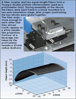
At Virginia Polytechnic Institute and State University (Blacksburg, VA) researchers have built a fiberoptic Young's double-pinhole interferometer for use as a three-dimensional (3-D) profilometer and in the process have developed a method of precisely equalizing the two fibers to create a stable zero-order fringe. In the interferometer, a fiber coupler splits light equally between two single-mode fiber sections, the output ends of which are placed to simultaneously illuminate a 3-D object. When imaged onto a charge-coupled-device (CCD) camera, the resulting fringe pattern on the object gives information on its surface profile. The phase ambiguity in the fringe pattern is eliminated by a phase-unwrapping algorithm that requires knowledge of the location of the zero-order fringe. To find such a fringe, two wavelengths—633 and 830 nm—are projected consecutively through the interferometer; if the path lengths are equal, the zero-order fringe is the one that does not move.
However, if the path lengths differ, even the zero-order fringe shifts. Thus, for the whole scheme to work, the two fiber sections must first be precisely polished to the same length. The researchers monitor the difference in length between the fibers during polishing by injecting broad-spectrum light from a superluminescent light-emitting diode (SLED) into the coupler. Backreflections from both fiber ends combined through the coupler are observed by an optical spectrum analyzer, revealing a modulated broadband spectrum having a modulation period that increases as the path-length difference decreases. Other system reflections and modal noise from the SLED introduce additional modulations that do not change during polishing and can be ignored.
Calculations show that a fiber-length difference of 6.6 µm produces a zero-order fringe shift of one CCD pixel—the chosen acceptance criterion. The fiber-polishing technique allowed the researchers to bring an initial fiber-length difference of 1 mm down to less than 6 µm (how much less remains unknown—a result of the limited width of the SLED spectrum). The small remaining length difference was compensated for by axially offsetting one of the fiber endfaces. Timothy Pennington, one of the researchers, notes that larger fiber-length differences cannot be compensated for using an axial offset without introducing an unacceptable fiber-dispersion-induced phase shift.
Simple in construction, the profilometer has been used to measure real objects (see image). Future avenues of research include the addition of a third wavelength—an additional reason to minimize affects of fiber dispersion, says Pennington.

John Wallace | Senior Technical Editor (1998-2022)
John Wallace was with Laser Focus World for nearly 25 years, retiring in late June 2022. He obtained a bachelor's degree in mechanical engineering and physics at Rutgers University and a master's in optical engineering at the University of Rochester. Before becoming an editor, John worked as an engineer at RCA, Exxon, Eastman Kodak, and GCA Corporation.