Commercial T-ray systems accelerate imaging research
David Zimdars
Fiber-coupled THz components have enabled new research in "T-ray" imaging. Potential applications range from "see-through" package inspection to portable 3-D scanners.During the past decade, new laser-based methods for generating pulses of far-infrared (far-IR) radiation at terahertz frequencies (0.1 to 10 THz) have been developed. These techniques have enabled a vigorous scientific investigation of this region of the electromagnetic spectrum. Now, commercial terahertz or "T-ray" instruments and components are reaching the market, intended for scientific and industrial uses such as spectroscopic measurement or process monitoring. The use of T-ray imaging to see through visually opaque materials, however, is perhaps one of the most exciting and actively investigated areas of the field.
Generation and detection of T-rays involves femtosecond laser pulses, which power paired photoconductive transducers. The technology was first pioneered at Lucent Technologies, Bell Labs (Holmdel, NJ) and IBM's Thomas J. Watson Research Center (Yorktown Heights, NY). Coherent emission and detection of T-ray pulses has largely replaced emission by thermal sources and detection by low sensitivity cryogenic bolometers. While the average power of T-rays is quite low, the very short pulses are instantaneously very bright. Whereas other far-IR imaging schemes might be swamped by thermal background,
The interaction of terahertz light with a given material is different from that of visible light. Nonpolar solids such as plastics and ceramics are at least partially transparent in the 0.2 to 5 THz range. Nonpolar liquids are transparent as well, whereas polar liquids, such as water, are highly absorptive. Metals completely block or reflect T-ray pulses. Gases can have distinctive spectroscopic fingerprints in the T-ray range. By analyzing the waveform in either the time domain (material homogeneity or thickness variations) or the frequency domain (frequency dependent absorption), images can be constructed by identifying properties such as thickness, density, and chemical composition.
So much to see
Published examples of T-ray imaging applications include using water content to identify raisins in a box of cereal, measuring the rate of water evaporation and uptake in leaves, examining circuit interconnects in packaged integrated circuits, reading text in envelopes or beneath paint, counting the number of almonds in a candy bar, identifying tooth decay, examining the top cellular layers of skin tissue, and identifying watermarks in various currencies.1, 2
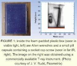
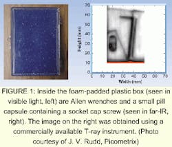
Terahertz imaging can be used in applications such as package inspection, quality control, or security (see Fig. 1). The interior contents of an opaque plastic or ceramic container that are invisible in visible light are visible within the T-ray transmission range. Until recently, T-ray imaging instruments were constructed from scratch by skilled laser researchers. Commercial T-ray systems, however, have recently become available.
One system available at Picometrix packages the discrete free-space optics of the originally cumbersome Bell Labs-style setup into a turnkey instrument using fiber-coupled T-ray transmitters and receivers. The full system consists of six modules: a modelocked Ti:sapphire laser, a fiber launch/dispersion precompensator, a T-ray optical gate scanning control box, a T-ray transmitter, a T-ray receiver, and an object raster scanner with focusing optics. A miniature T-ray transmitter and receiver are at the heart of the technology. These modules are packaged using standard telecom technology, and are hermetically sealed with permanently aligned fiberoptic pigtails.
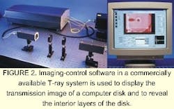
To make an image, the operator affixes the object of interest to a raster scanner. Using the accompanying software, the operator defines the image area to be scanned, the desired resolution, and the type of waveform analysis (time domain, frequency, and so on. The software then scans the object through the T-ray focus, recording a full T-ray waveform at up to 10 pixels per second (see Fig. 2). Typical scans can be completed in 10 minutes. The computer generates the image from the data using the selected analysis, and can regenerate images using different analyses without reacquiring the data.
Terahertz pulses are very nearly single-cycle optical pulses. The pulse electric field starts at zero, becomes positive, then negative, and then zero again with very nearly one oscillation. The T-ray pulses can be detected via transmission or reflection with signal-to-noise ratios better than 1000:1. Terahertz imaging has better resolution than microwaves, is not potentially dangerous like x-rays, and does not need to contact the object like ultrasound.
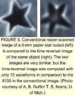
T-ray receivers record the electric field as a function of time with a resolution that is a small fraction of a terahertz wave cycle. Conventionally, the absorption of the pulse is measured to form an image. Recently, however, several researchers have used the extraordinary time resolution inherent in a T-ray waveform to generate images with better depth resolution and without raster scanning. The T-ray analogs of magnetic resonance imaging, pulsed ultrasound, and other tomagraphic techniques are now being developed.
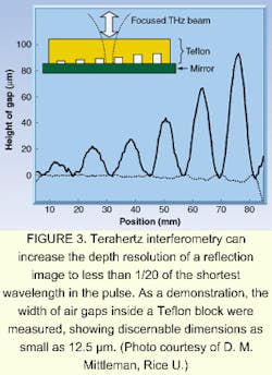
Ordinarily, the best resolution of a T-ray image is slightly less than 100 µm laterally. This is because the terahertz light can be focused only to the width of its shortest wavelength. To achieve much better depth resolution, researchers at Rice University (Houston, TX) have performed T-ray interferometry by precisely recording the T-ray electric field in time.3 In this technique, the T-ray pulse is split into two parts. One pulse travels through a reference path; the other reflects off the surface of a sample. The two pulses are recombined so that at zero sample height, the difference in the reference and sample path lengths results in 180° phase-shift and the T-ray pulses destructively interfere. At zero height, the receiver detects no signal. When the sample is moved, slight changes in the surface height will negate the cancellation, and the receiver will detect a signal (see Fig. 3).
Time reversal
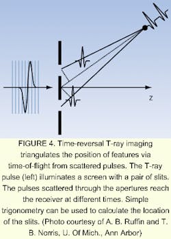
In an exciting development that may allow T-ray imaging to abandon the time-consuming and cumbersome process of raster scanning objects, researchers at the Center for Ultrafast Optical Science at the University of Michigan in Ann Arbor have demonstrated a new method called time-reversal T-ray imaging.4 In this casae, the object is broadly illuminated with a T-ray pulse. The T-ray waveform scattered from the object is measured at several angles. The scattered T-ray pulses traveling from each location on the object take different times to reach the receiver. The signal waveform is back-propagated by a computer program to calculate what kind of object must have scattered the T-rays (see Fig. 4).
Terahertz time reversal can image complex two-dimensional (2-D) objects by rotating the receiver radially around the plane of the object, and triangulating the combined data sets by computer. Commercial fiber-pigtailed T-ray receivers make the repositioning of the receiver practical. Without fiberoptics, the realignment of the free-space laser beams powering the T-ray antennas would be extraordinarily complex and time consuming. Further development of the time-reversal T-ray method in coming years could lead to fully portable T-ray imaging equipment capable of capturing a 3-D scan in less than a second.
REFERENCES
- Q. Chen, Z. Jiang, and X.C. Zhang, SPIE 3617, 98 (1999).
- D. M. Mittleman et al., Appl. Phys. B 68, 1085 (1999).
- J. L. Johnson, T. D. Dorney, and D. M. Mittlemean, Appl. Phys. Lett. 78, 835 (2001).
- A. B. Ruffin et al., Opt. Lett. 26, 68 (2001).
DAVID ZIMDARS is the manager of terahertz product research and development at Picometrix Inc., PO Box 130243, Ann Arbor, MI 48113-0243; e-mail: [email protected].
