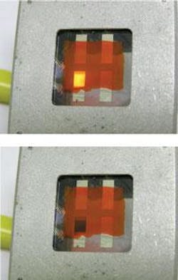
Dual display exhibits reflective and emissive modes

Although polymer light-emitting devices (PLEDs) offer wider viewing angles, broader color range, and lighter weights than liquid-crystal displays (LCDs), they can only operate in power-consuming emissive mode. And while LCDs can be illuminated by ambient light in power-saving or reflective mode, as well as operate in emissive or backlit mode, their display performance is poorer than that of PLEDs. Now researchers at The Chinese University of Hong Kong (Hong Kong, China) have developed a novel polymeric flat-panel display device that offers the superior performance of PLEDs and the energy-saving functions of LCDs.1
The dual emissive and reflective display functions as a light-emitting electrochemical cell formed from a blend of electroluminescence (EL) polymer with a solid electrolyte in the emissive mode and an electrochromic (EC) cell formed from a blend of EC polymer with a solid electrolyte in the reflective mode. Switching between modes is accomplished by varying the polarity of the applied voltage to a sandwich of these materials between two electrodes.
When voltage is applied to a light-emitting electrochemical cell, charge injection from the electrode results in the formation of p- and n-doped regions adjacent to the anode and cathode, respectively. Recombination of electrons and holes in the insulating region of the p-i-n junction then gives rise to light emission of the polymer.
To achieve both emissive and reflective modes, an EC polymer blend is first spin-coated on top of an indium tin oxide (ITO)-coated glass substrate, baked to dryness, and then followed by spin-coating and baking of a second layer of EL polymer blend. Next, a silver (Ag) film is thermally deposited in a vacuum on top of the EL blend to serve as the counterelectrode. The resulting ITO/EC/EL/Ag sandwich is then covered by a glass plate and sealed with epoxy.
EL helps EC, and vice versa
The dual emissive and reflective capability is enabled by a complex interaction between the two polymer materials as a function of applied voltage. Depending on the bias voltage, which is defined to be positive if the ITO terminal is connected to the anode, the EC polymer blend serves as the electrochromic material and as the hole-transporting electron-blocking layer for the EL polymer blend. Conversely, the EL polymer blend serves as the emissive material and also as the ion-storage layer for the EC polymer.
When the voltage is positively biased, electrons are injected from the Ag electrode to the adjacent EL layer making this region an n-type. Concurrently, holes injected from the ITO are transported through the EC layer to the EC-EL boundary, making the adjacent EL region p-type. In this case, a p-i-n junction is formed and the display becomes emissive.
Under a negative bias, however, only a very weak electron current through the EC layer is possible due to its electron-blocking characteristics. The minimal charge injection across the EC-EL boundary means that no p-i-n junction is formed and no light emission occurs. Concurrently, the EC polymer, which is normally a transparent film, turns a deep blue color when it is electrochemically reduced or de-doped.
Experiments on a fabricated display showed light emission of an orange color with 3.6-V biasing, and dark blue or reflective mode with a bias of -1.6 V (see figure). Because different colors are available for EC and EL films, a proper combination of materials in the form of an active or passive matrix could allow full-color display.
“We believe this device should have good commercial potential,” says Professor King Y. Wong at the Department of Physics at the Chinese University of Hong Kong. “Currently, the major problems are its poor switching speed and long-term stability. We hope that a solution can be found to enhance the performance in these two aspects in the future.”
REFERENCE
1. X.J. Wang et al., Applied Phys. Lett. 87, 113502 (2005).

Gail Overton | Senior Editor (2004-2020)
Gail has more than 30 years of engineering, marketing, product management, and editorial experience in the photonics and optical communications industry. Before joining the staff at Laser Focus World in 2004, she held many product management and product marketing roles in the fiber-optics industry, most notably at Hughes (El Segundo, CA), GTE Labs (Waltham, MA), Corning (Corning, NY), Photon Kinetics (Beaverton, OR), and Newport Corporation (Irvine, CA). During her marketing career, Gail published articles in WDM Solutions and Sensors magazine and traveled internationally to conduct product and sales training. Gail received her BS degree in physics, with an emphasis in optics, from San Diego State University in San Diego, CA in May 1986.