INTERFEROMETRY: Interferometry moves beyond controlled laboratory environments

CHIP RAGAN and ERIN McDONNELL
Quantitative metrology solutions—notably laser interferometers—have been commercially available for more than 30 years, providing noncontact three-dimensional (3D) surface and optical wavefront mapping for a wide range of markets and applications. These tools provide accurate, nanometer-level details of form and shape across a variety of components, including a diverse assortment of optics. Vibration and turbulent airflow have often limited-or even precluded-the application of these metrology instruments outside of dedicated laboratory environments.
Recent advances have enabled a new generation of instrumentation to extend the range of environments for 3D optical metrology. Several techniques expand the use of interferometers beyond the laboratory, including single-frame spatial phase-shifting and robust temporal phase-shifting methods. Each implementation has strengths and weaknesses depending upon the application. Here we provide an overview of various quantitative 3D metrology solutions for adverse environments to facilitate identifying the best choice for a given application.
Metrology measurement challenges
Interferometric measurements use the precision inherent in the wavelength of light for surface characterization. An unintended consequence is that traditional interferometers are also sensitive to environmental disturbances, particularly vibration and rapid airflow. Interferometry relies on superimposing the light reflected from a reference surface with the light reflected from a part under test. This results in a series of black-and-white fringes representing contour lines that follow the surface height profile.
In temporal phase-shifting interferometry, three or more fringe patterns acquired at a known phase offset produce a precise contour map of the surface. However, if those fringes are unstable due to environmental factors, the uncontrolled motions induce errors in the phase calculation and result in an inaccurate representation of the part under test.
The traditional solution to vibration problems has been to isolate the instrument from the environment. Rigid isolation structures and devices built to passively mix air can eliminate enough of the uncontrolled motions and airflow to obtain reliable results. Sometimes these precautions necessitate entirely separate metrology rooms or dedicated control areas. While these solutions provide excellent results, they are not appropriate for the full range of potential applications and can be expensive.
Mechanical vibrations introduce rigid body motion that changes the location and orientation of the part, introducing uncontrolled modulations in the fringe pattern. These errors manifest as a fringe "print through" pattern in the final surface height map, generally at twice the spatial frequency of the fringes. At high vibration levels, fringes may even wash out and the measurement may fail entirely.
High-velocity nonlaminar airflow can also cause complications in metrology, resulting in localized, swirling changes in fringes. Slower-moving changes, such as fringe drift, indicate changes in thermal conditions. The faster-moving perturbations are caused by air conditioning or filtration systems. Metrology equipment designed for a controlled environment may not be viable in such unstable settings with unacceptable variability from measurement to measurement.
Optical shop floor
With the trend toward tighter component-level tolerances, testing is increasingly required for volume optics manufacturing. Since throughput and process control are critical, metrology tools must be located in close proximity to process equipment, minimizing part handling time. This also allows operators to directly monitor process trend information, enabling early identification of specification drift and proactive adjustment of critical process control parameters to prevent production of out-of-tolerance components.
Mechanical vibration issues are common in production environments with heavy machinery. On the shop floor, metrology space is a key factor; thus, it is not always practical or preferable to fill that space with bulky vibration isolation tables. Cost and throughput are also vitally important; therefore, a system requiring critical and complex setup is less than ideal.
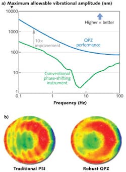
Robust, vibration-resistant acquisition technology is now available in instrumentation with a smaller footprint designed specifically for use on the volume production floor. In recent years, interferometer technology has advanced past traditional phase-shifting interferometry with robust phase acquisition techniques that are less sensitive to vibration without compromising performance. A good instrument can show a 10X improvement in vibration immunity (see Fig. 1).
A robust instrument will not show the telltale fringe print through that would be observed in the phase map of a traditional instrument in a vibrating cavity. These advances are key enablers to bring metrology to the optical shop even with vibrating machinery nearby.
Dynamic instrumentation
Manufacturing lower-volume but high-value optical components and systems has its own metrology challenges. Quality and reliability are imperative as these systems are often intended for mission-critical applications and/or used in remote or inaccessible locations. Imaging systems used for defense intelligence, surveillance, and reconnaissance (ISR) and astronomy applications are prime examples; they require the highest performance available but must operate at high altitudes, on remote mountaintops, and even in the vacuum of outer space.
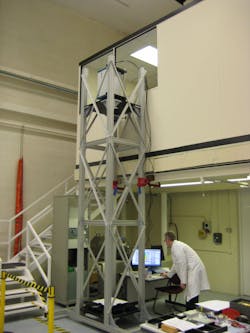
These systems often have large, concave primary mirrors with long radii of curvature. Testing requires the metrology equipment to be separated from the test part, often by tens of meters (see Fig. 2). The long test cavities introduce significant turbulence to the measurement. In addition, the physical separation is highly susceptible to mechanical vibration. These levels of disturbance are beyond the capability of even robust instruments and require the use of dynamic measurement systems.In these extreme environments—where vibration and/or turbulence cause the fringe pattern to shift more than a fringe—conditions are so severe that there is simply no time to acquire data because of the constant movement. In this case, all information required for interference fringe analysis must be gathered instantly. For these cases, "dynamic" interferometry—another universally known term—achieves localized spatial phase shifting in a single-frame interferogram, effectively freezing any turbulence or vibration effects. A proven method for introducing a localized spatial phase shift is using dense carrier fringes. An alternative configuration employs polarization encoding of the reference and measurement beams as well as specialized camera hardware to introduce phase shifts between camera pixels. Fortunately, state-of-the-art dynamic instruments are capable of low-noise acquisition in less than 15 μs, easily acquiring a phase map free from environmentally induced dropout.
Single-frame dynamic data acquired in difficult environments contain aberrations caused by the environmental disturbances. These are minimized by averaging multiple single-frame datasets, effectively suppressing the unwanted aberrations and converge to provide only the optical component information. Depending on the severity, the acquisition time required to average out environmental effects can be significantly longer but is acceptable for lower-volume situations.
The amount of averaging performed directly affects the uncertainty of the measurement. This can be difficult to quantify; therefore, systems now include a Convergence Mode that observes measurement uncertainty and spatial deviations from measurement to measurement, providing graphical feedback to monitor progress. Acquisition automatically stops after reaching the desired measurement precision.
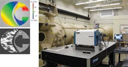
In some test cases, rather than simply averaging data to remove environmental variations, it is useful to actually measure and capture the environmental changes over time. For such tests, a movie mode can create a video of the airflow changes captured in a height map. In movie mode, the system can acquire up to 50 frames/s and store the results in an .avi file. A wind tunnel test is an example of an application using movie mode-the video captures how air flows over the test part (see Fig. 3). Measurements of deformable mirrors and adaptive optics can also use this methodology. A dynamic instrument equipped to display a height map in real time, with live measurement capability, can be particularly useful for optical assembly alignment and testing. A real-time map with continuously updated Zernike coefficients facilitates adjustments that eliminate alignment aberrations such as coma.And yet there are still a few drawbacks to using dynamic technology. Dynamic interferometers pay for their unique functionality at the expense of the lateral resolution. Higher-resolution cameras can gain back resolution but this may not be sufficient for applications requiring full characterization of the power spectral density (PSD). To characterize PSD, a true optical zoom is the best solution. A further consideration is calibration, which is essential for any high-precision measurement. Dynamic interferometers require additional calibration procedures in comparison to traditional phase-shifting systems. Carrier fringe methods employ in situ calibration that makes use of the part under test, and wizard-driven software simplifies and optimizes this process to minimize the increase in initial setup time.
Surface form measurement requirements have evolved to allow precise metrology in less than ideal environments. Instead of being a controlled process in a specially built room, metrology is increasingly being required directly on the production floor. Interferometers have adapted to fit the needs of various environments. In selecting an interferometer, first recognize the environment in which it is to be used and what unique challenges that environment produces, then choose the instrument best suited to fill those needs.
ACKNOWLEDGEMENT
Zygo is a registered trademark of Zygo Corporation. Verifire and DynaFiz are trademarks of Zygo Corporation.
Chip Ragan is the director of product marketing and Erin McDonnell is an applications engineer at Zygo Corporation, Laurel Brook Rd., Middlefield, CT 06455; e-mail: [email protected]; www.zygo.com.

