Optics/Advanced Microscopy: Practical considerations for advanced microscopy
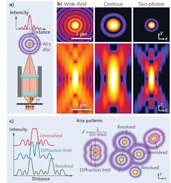
As little as a decade ago, advanced approaches such as total internal reflection fluorescence (TIRF) and super-resolution microscopies were largely the domain of physicists, optical engineers, and cross-disciplinary scientists and researchers. Thanks to the increasing availability of commercial turnkey systems, access to such techniques has greatly expanded, boosting scientific progress worldwide.
But even occasional users can benefit from knowledge of the equipment's technical underpinnings, particularly regarding practical-use considerations that straddle the boundaries between theory and practice. Let's take a look at some key optics considerations that will help maximize image fidelity and quality, light transmission, and resolution, thereby enabling data reliability.
High NA objectives
Using objectives with the highest numerical aperture (NA) available for a given magnification will maximize microscope resolution.
Consider two miniscule fluorescent particles, spaced very closely together. To resolve these particles as discrete units, a microscope must be able to image them at their true size. The physics of light passing through lenses, however, means the optics will capture each particle as a three-dimensional blur known as the point-spread function (PSF; see Fig. 1). The maximal resolution in the x-, y-, and z-directions will be achieved when these PSFs are as close as possible to the actual size of the particle, and physics dictates that higher NA objectives produce smaller PSFs.
The highest achievable NA typically increases with objectives' magnification and degree of correction for optical aberrations, and with oil (over dry) lenses—it has practical and theoretical limits in the 1.4–1.7 NA range. (Since an objective's NA is a product of its light collection ability and the refractive index [RI] of the immersion media, high RI oils produce the highest NAs.) The XY resolution limit of ~0.25 μm for diffraction-limited microscopy can be improved about tenfold to ~0.025 μm (25 nm) with some super-resolution microscopy techniques.As can be inferred from the shape of the PSF, resolution in the z-direction with the highest NA lenses is only about half as good (~0.5 μm), which also may improve tenfold or more with some super-resolution technologies. (Many super-resolution microscopy approaches only marginally increase z-axis resolution as opposed to the greater gains typically achieved in x-y resolution.1) Higher NA lenses also increase light transmission (thus maximizing system sensitivity) and typically are maximally corrected plan apochromat lenses, which increase color fidelity, improve image quality, and reduce pixel shift (image registration). While maximizing lens NA always maximizes x-y-z resolution, sometimes more moderate NAs may be preferred, such as when larger depth of field is desired or for deep tissue imaging.
Dichroic flatness
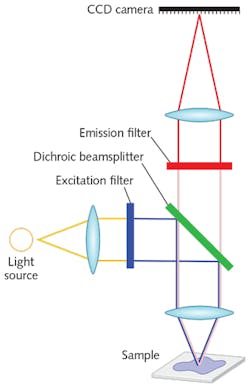
In a typical epifluorescence microscope, the dichroic beamsplitter reflects lower wavelength excitation light to the sample and transmits higher wavelength emitted fluorescence from the sample to the detector (see Fig. 2).
Dichroics should have high transmission and reflectivity, high edge steepness with edges keyed to laser wavelengths, good antireflective coating on the back surface, low autofluorescence glass, high laser damage thresholds, and low transmitted wavefront error (TWE).2 But the key feature of dichroics that enables most advanced imaging techniques is flatness. Insufficiently flat dichroics in the excitation or emission path can compromise image quality and uniformity, resolution, pixel alignment, and signal-to-noise ratio (SNR), and thus may impact data interpretation, reliability, and quantifiability. TIRF and super-resolution microscopy, by their nature, are especially sensitive to the effects of dichroic aberrations.
In TIRF, any curvature in a dichroic will cause astigmatism in the beam profile, resulting in light entering the sample at various unexpected angles—thus increasing background fluorescence and reducing SNR.3 Significant bending or surface irregularities may even make it difficult to achieve TIRF, or contribute to interference fringing.4
Similar considerations may apply for other super-resolution approaches. In structured-illumination microscopy (SIM), one of the more flexible and user-friendly of these approaches,5 correcting system astigmatism has been shown to significantly improve optical resolution.6 Therefore, using the flattest possible dichroics to minimize astigmatism should lead to tangible gains.
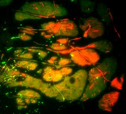
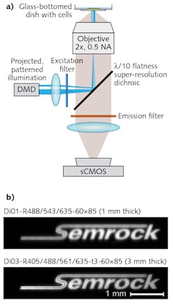
Any astigmatism or other aberration will reduce effective resolution, as such optical aberrations will alter spot size and/or shape from the ideal diffraction-limited PSF provided by a perfectly flat dichroic. New dichroics with λ/10 (0.1 waves/in.) peak-to-valley (P-V) flatness (on 3-mm-thick glass) and λ/2 (0.5 waves/in.) P-V flatness (on 1-mm-thick glass) address such needs, and benefit such imaging techniques as TIRF, SIM, PALM, STORM, STED, GSDIM, SPIM, MUM, patterned illumination, laser-based confocal microscopy (see Fig. 3), and even LED or broadband light source-based super-resolution techniques (see Fig. 4).Stimulated emission depletion (STED) microscopy is extremely sensitive to optical aberrations that alter the expected size, shape, or regularity of the excitation and depletion beams, particularly the "donut-shaped" depletion beam. We have identified astigmatism as the dominant optical aberration of insufficiently flat beamsplitters,7 and some have found that the donut-shaped depletion beam required for STED is so sensitive to the effects of astigmatism that "in the presence of astigmatism, the focal fields are already so distorted that these two patterns probably would be useless for super-resolution optical microscopy."8 So for successful and reliable STED, dichroic flatness is critical. While these flatness considerations apply to both pulsed and continuous-wave (CW) STED, pulsed STED may require additional optimization of optics for use with ultrafast lasers.
Optical astigmatism introduces a predictable change in the shape (ellipticity) of the PSF that varies with the depth of the PSF in the sample. In other words, the exact shape characteristics of an astigmatism-altered PSF provide precise information about its location in the z-axis. So by deliberately introducing astigmatism in a known and controlled manner, this physical behavior of the PSF can be harnessed to reconstruct axial (z-axis) resolution with sub-diffraction precision. An early implementation of this approach, 3D-STORM, relies on astigmatism introduced by a cylindrical lens.9 Similar approaches described more recently have used deformable mirrors to introduce controlled astigmatism and achieve similar resolution-improving effects.10
When choosing optics to use for introducing the desired (i.e., controlled) astigmatism to accomplish super-resolution imaging, it is important to consider that unwanted astigmatism must therefore be minimized or eliminated for these and similar methods to provide accurate, reliable localization and resolution information. Therefore, dichroics should introduce minimal wavefront distortion.Many techniques are currently being driven by needs for increasing throughput, imaging larger fields of view, or using larger-diameter illumination beams (as with LEDs) that require even greater flatness to maintain imaging quality. New λ/10 flatness dichroics allow use of large beam diameters with minimal impact to the reflected beam—up to 22.5 mm for reflected laser beams (e.g., TIRF) and up to 37 mm for reflected imaging beams (e.g., SIM) at 633 nm.11 Based on his recent experience, Kit Werley of Q-State Biosciences (Cambridge, MA) stated that Semrock's 3-mm-thick λ/10 Flatness dichroic "effectively eliminates aberrations when using an LED excitation source and imaging a micromirror array onto the sample for optogenetic stimulation of single neurons [see Fig. 4]."
Use of standard-thickness (1 mm) glass means that for many advanced microscope systems, ultra-flat dichroics can simply "drop in place" in industry-standard cubes, thus facilitating their use as cost-effective system upgrades. It is important to note that careful mounting of dichroics in filter cubes and holders is critical because flatness may be significantly altered by torques and other stresses, particularly when the mounting platform or cube is not specifically engineered to maintain flatness. New super-resolution microscopy cubes from Semrock are guaranteed to maintain flatness specifications of such 1-mm-thick dichroics—their use leads to minimal beam shift and light scatter in transmission, and avoids need for realignment that might be required if one were switching between cubes holding dichroics of different thicknesses.12
Excitation and emission filters
It is important to select excitation and emission filters for the highest transmission characteristics and high blocking (>OD6) of any stray excitation light that will reduce SNR if allowed to reach the detector.
Because lasers are usually not 100% spectrally pure but often contain signal at other wavelengths, using a laser clean-up filter (exciter) can decrease background and increase SNR. While placing such a filter at the laser head is typically recommended, this location can be impracticable, particularly for fiber-based systems. In TIRF systems, for example, which are often supplied without an excitation filter in the filter cube, the laser clean-up filter can often be installed there. Whenever possible, clean-up filters should be offset by 2–3° on optical benchtop systems to prevent back-reflections into the laser cavity, a danger that increases the closer the filter is to the laser.
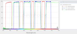
Another critical aspect is to ensure that the exciter and emitter have complimentary transmission and blocking requirements. Additionally, optimizing the spectral edges of all the filters helps assure the best possible SNR. Such design needs are provided in a standard filter set configuration that includes an exciter, emitter, and dichroic filters (see Fig. 5). Many setups use individual filters rather than filter sets—Semrock's SearchLight tool (see https://searchlight.semrock.com) enables evaluation of signal and SNR tradeoffs in such imaging setups.Finally, the combination of emitters and dichroics in the emission path of a microscope significantly impacts pixel-shift (image registration) performance between different colors. Multicolor super-resolution techniques demand sub-pixel image registration. Despite technical advances in optical and mechanical components, sub-pixel image registration needs (for example, 1/10th) are best handled by software processing.
While this article presents practical tips for optimizing microscopy systems and data collection, it is not an exhaustive discussion of these topics. An in-depth white paper, providing greater detail gleaned from both theory and hands-on experience, will be available by the end of 2016 at www.semrock.com.
REFERENCES
1. L. Schermelleh, R. Heintzmann, and H. Leonhardt, J. Cell Biol., 190, 2, 165–175 (2010).
2. See "Optical filters for laser based fluorescence microscopes," http://bit.ly/2ccLZt.
3. A. Yildiz and R. D. Vale, Cold Spring Harb. Protoc., 9, 801–810 (2015).
4. P. Prabhat and T. Erdogan, BioOptics World (Jan/Feb. 2009); see http://bit.ly/2bZiKyD.
5. J. A. Thorley, J. Pike, and J. Z. Rappoport, "Super-resolution microscopy: A comparison of commercially available options," Fluorescence microscopy: Super-resolution and other novel techniques, Elsevier Inc., 199–212 (2014).
6. D. Debarre, E. J. Botcherby, M. J. Booth, and T. Wilson, Opt. Express, 16, 13, 9290–9305 (2008).
7. See "Flatness of dichroic beamsplitters affects focus and image quality," http://bit.ly/2ccLZtT.
8. S. Deng, L. Liu, Y. Cheng, R. Li, and Z. Xu, Opt. Express, 18, 2, 1657–1666 (2010).
9. B. Huang, W. Wang, M. Bates, and X. Zhuang, Science, 319, 5864, 810–813 (2008).
10. I. Izeddin et al., Opt. Express, 20, 5, 4957–4967 (2012).
11. See "Practical flatness," Semrock Wavelengths Newsletter, 7, 1 (Apr. 2016); http://bit.ly/2ccMTX1.
12. H. C. Ishikawa-Ankerhold, R. Ankerhold, and G. P. Drummen, Molecules, 17, 4, 4047–4132 (2012).
13. A. Diaspro et al., Biomed. Eng. Online, 5, 36 (2006).
14. See http://bit.ly/1GZ2EOO.

Prashant Prabhat, Ph.D. | Business Line Leader for Semrock Catalog
Prashant Prabhat, Ph.D. is Business Line Leader of Catalog Business at Semrock. Since 2008 he has been an Applications Scientist at Semrock. He earned his Ph.D. in Electrical Engineering from the University of Texas at Dallas and completed graduate research at Ward Lab at the University of Texas Southwestern Medical Center. It was there that he invented multifocal plane microscopy (MUM), a technique that allows for real-time visualization of fast cellular dynamics in 3D. MUM has enabled the discovery of novel trafficking pathways in cells, and formed the basis for 3D super-resolution techniques. At Semrock, he advises researchers on optical filter issues from a systems perspective, and helps develop the company’s product roadmap. As a new venture manager, he also has led the development of a computer controlled tunable filter system.
Seth W. Perry | Founder, Veroptics LLC
Seth W. Perry is a research scientist, writer, technology consultant, and founder of Veroptics LLC (Pittsford, NY).
Jim Passalugo | Business Line Director, Semrock
Jim Passalugo is business line director at Semrock, a unit of IDEX Health & Science LLC (Rochester, NY).
