Fluorescence Microscopy: Optimizing the imaging performance of LED light engines
Thanks largely to performance gains and commercial availability, sources based on light-emitting diodes (LEDs) are displacing traditional gas-discharge lamps in fluorescence microscopy systems. Advantages of LED "light engines" include long lifetime, stable output, electronic fine tuning of output intensity, and rapid electronic switching between wavelengths. "As LED light engines are finding applications in single-molecule imaging, it is critical to use appropriate filters that can produce very high SNR," says Professor Douglas Shepherd at the University of Colorado Denver.
Regardless of the type of light source used in an experimental setup, a microscopist generally aims to capture high-quality images—that is, images with bright signals and minimal noise. Thin-film optical filters play a key role in optimizing signal-to-noise ratio (SNR) by transmitting light at the desired wavelengths for excitation or detection, and blocking unwanted wavelengths. In an effort to improve SNR, LED light engines are now available with integrated excitation filters to narrow their output to only the wavelengths of highest intensity. To do so effectively, however, requires consideration of the other optical filters within the system as well.
Microscopy filters
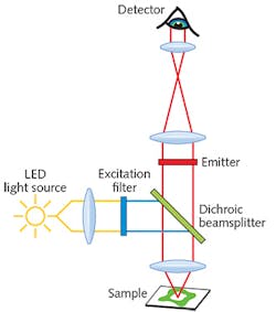
Three main types of filters are used in fluorescence microscopy: an excitation filter, a dichroic beamsplitter, and an emission filter (see Fig. 1). The excitation filter controls the light that illuminates the sample. It allows light of desired wavelengths from the light source to pass through and reach the sample, and blocks light of unwanted wavelengths. The emission filter works similarly, but controls the light that is recorded by the detector. It allows the desired fluorescence signal emitted by the sample to pass through and reach the detector, and blocks light of other wavelengths. The third type of filter, the dichroic beamsplitter, is positioned between the excitation and emission filters. It reflects the illumination light transmitted by the excitation filter, directing it to the sample, and also transmits the light emitted by the sample, directing it through the emission filter for detection.There are two approaches to selecting the best filter combination for a given fluorescence experiment. The first is to use a standard catalog "filter set," in which the excitation, emission, and dichroic beamsplitter filters are bundled in a combination designed to provide the best overlap and efficiency when used with a given fluorophore and illumination source. Filter sets are available for all commonly used fluorophores, but a stumbling block for LED light engine users is that most have been optimized for illumination with traditional mercury-arc, metal-halide lamps, or laser sources.
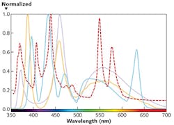
That's important because different light sources are characterized by different spectral power distributions. Thus, filter sets designed for traditional gas-discharge lamps may not provide optimal performance when used with LED light sources. Figure 2 shows the very different normalized power spectra for a traditional metal-halide lamp and three possible LED light sources, underscoring the importance of tailoring the filter set to the illumination source.The second approach to designing a fluorescence microscopy experiment is to individually select the excitation filter, emission filter, and dichroic beamsplitter. Although this allows the opportunity to optimize for the unique spectrum of the LED light engine, one needs to essentially design the custom filter set, carefully navigating trade-offs between performance and filter availability. Factors to consider include overlap with the light source and fluorescence emission spectrum, position of the dichroic beamsplitter edge, and crosstalk or bleedthrough between channels.
Evaluation and optimization
How does one even begin to plot and evaluate the compatibility of filters for a particular combination of LED light engine and fluorophore(s)? To do so quantitatively in a spreadsheet format requires that the excitation and fluorophore spectra be multiplied against the appropriate filter spectra, after which the convoluted spectra must be integrated over the relevant wavelength ranges to calculate signal and noise.
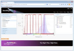
Sounds like a job for a clever software app, right? Indeed, Semrock's freely available web-based SearchLight tool (www.searchlight.semrock.com) simplifies the process by plotting the spectra of filters, fluorophore(s), and light sources concurrently (see Fig. 3). Data for more than 600 fluorophores is available, as are emission spectra for a wide variety of light sources, including popular LED light engines. In addition to evaluating Semrock filters, users can also privately load their own data for any system component. Once a filter set has been configured in SearchLight, the tool allows the user to perform quantitative analysis of signal and SNR to evaluate compatibility for a given application and enable comparisons to alternate filter sets.When designing a custom filter set for use with an LED light engine, it is important to choose an excitation filter with a transmission band that overlaps sufficiently with the peak of the LED source's spectral emission. This will more fully utilize the LED light source to obtain a bright fluorescence signal from the sample.
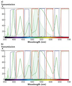
The impact of excitation filter optimization can be seen in Fig. 4. In Fig. 4a, the excitation filter (dashed blue line) clips the LED source spectral peak at ~480 nm. In Fig. 4b, the excitation filter has been replaced with a filter that overlaps the LED light source's spectral peak more effectively. In doing so, the amount of excitation light has increased and, hence, 40% more fluorescence signal from the FITC-labeled sample can be expected.It is also important to select an emission filter having a transmission band that is well-matched to the peak fluorescence emission wavelengths. The dichroic beamsplitter is then chosen to complement the other two filters, with a reflection band spanning the excitation filter wavelengths and a transmission band passing the full range of emission filter wavelengths.
Larger passbands can allow more light of neighboring wavelengths to pass through the excitation and emission filters, thereby increasing the overall brightness of the image. However, simply increasing the bandwidth of the filters to maximize the output of the LED Light engine or fluorescence emission spectrum may not result in best fluorescence signal and signal-to-noise. This is because there are inherent trade-offs between brightness, contrast, and bleedthrough. Depending on the particular experimental settings, the net effect could be a reduced signal-to-noise ratio, and therefore an image with poorer contrast. A tool like SearchLight helps to quickly and quantitatively evaluate filter options to maximize performance.
Improved brightness, SNR
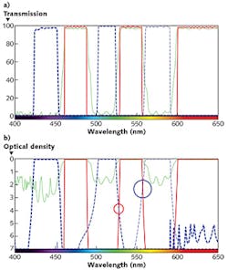
While matching the wavelength bands of the filter set to the light source and fluorophore is critical for ensuring a bright fluorescence signal, edge steepness of the filters also plays an important role, particularly in the cross-over region between excitation and emission. When imaging a fluorophore with an excitation peak and an emission peak that are close together, the use of filters with steep edges is crucial to achieve sufficient isolation of the fluorescence signal from the excitation light. When the cross-over edges of the excitation and emission filters of a mix-and-match filter set overlap (marked by circles in Fig. 5b), the excitation light can leak into the emission channel, thereby compromising image signal-to-noise.This crosstalk evaluation can be performed properly only by plotting the spectra of filters on a logarithmic optical density (OD) scale—as even excitation light leakage on the order of 10-4 can impact image quality. As can be seen in Fig. 5, filters that appear to be well-separated on a traditional transmission scale can have significant overlap when plotted in OD. In an optimized filter set, crossover between the transmission bands of the excitation and emission filters should provide OD > 6 blocking. This improves the image quality by reducing the amount of excitation light being passed through to the detector as background noise.
The crosstalk observed in mix-and-match filter sets can result in high or non-uniform background and poor image quality (see Fig. 6). An optimized filter set, however, yields a dark, uniform background and better image quality.Filters with steep edges allow the transmission bands of the excitation and emission filters to be maximized, while still minimizing crossover between the two. Whether adapting an LED light engine equipped with an excitation filter to an existing filter set, or creating a new mix-and-match filter set, the design considerations involved in optimizing filter sets can be daunting to most non-optical engineers and biologists.
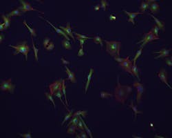
To simplify the process of selecting a filter set for use with an LED light engine, Semrock has developed a dedicated product line of filter sets optimized for use with popular LED light engines. Available for many popular fluorophores in single-band, multi-band, Pinkel, and Sedat configurations, these LED filter sets take the guesswork out of configuring a microscope equipped with an LED light engine, and ensuring bright, clear images (see Frontis).
As LED light engines become more popular, it is important to re-examine the design of the filter sets with which they are used to avoid degradation of SNR and background image quality. The daunting task of optimizing a mix-and-match LED light engine filter set can be greatly simplified through the use of online calculation tools—and taking the process one step further, Semrock's off-the-shelf BrightLine Highest Performance filters, including the LED light engine product line, provide instant solutions for virtually any fluorescence microscopy application.
Acknowledgements
BrightLine is a trademark and registered trademark of Semrock, and XLED is a registered trademark of Excelitas Technologies.
REFERENCES
1. P. Prabhat, "Filter sets for LED-based light-engine microscopy" (2015); see http://bit.ly/1GIyTLM.
2. P. Prabhat, "Maximizing fluorescence performance with LED light engine filters" (2015); see http://bit.ly/1LvdMVu.
About the Author

Prashant Prabhat, Ph.D.
Business Line Leader for Semrock Catalog
Prashant Prabhat, Ph.D. is Business Line Leader of Catalog Business at Semrock. Since 2008 he has been an Applications Scientist at Semrock. He earned his Ph.D. in Electrical Engineering from the University of Texas at Dallas and completed graduate research at Ward Lab at the University of Texas Southwestern Medical Center. It was there that he invented multifocal plane microscopy (MUM), a technique that allows for real-time visualization of fast cellular dynamics in 3D. MUM has enabled the discovery of novel trafficking pathways in cells, and formed the basis for 3D super-resolution techniques. At Semrock, he advises researchers on optical filter issues from a systems perspective, and helps develop the company’s product roadmap. As a new venture manager, he also has led the development of a computer controlled tunable filter system.
